EVPN Designs: Scaling IBGP with Route Reflectors
In the previous blog posts, we explored the simplest possible IBGP-based EVPN design and tried to figure out whether BGP route reflectors do more harm than good. Ignoring that tiny detail for the moment, let’s see how we could add route reflectors to our leaf-and-spine fabric.
As before, this is the fabric we’re working with:
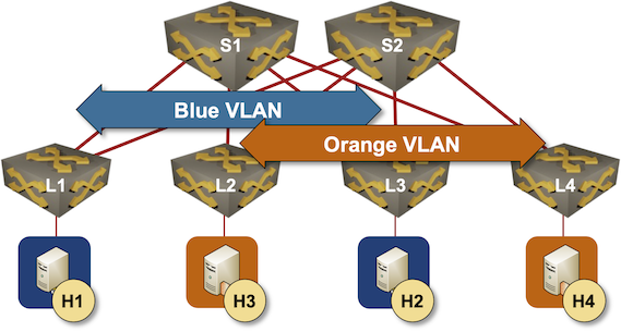
Leaf-and-spine fabric with two VLANs
As we’re discussing an IBGP-based design:
- Leaf- and spine switches are running OSPF
- IBGP is used solely to transport EVPN address family.
The crucial question for today’s discussion is where to place the route reflectors and whether we can use spine switches as route reflectors.
The CPU load on spine switches is usually pretty low (assuming they do packet forwarding in hardware), so they seem to be the perfect candidates for BGP route reflectors. There are just a few reasons why one wouldn’t do that:
- You bought spine switches that do IP forwarding but don’t support EVPN.
- You didn’t want to pay for the EVPN license on the spine switches.
- You bought leaf- and spine switches from different vendors and are worried about interoperability.
- Your network has so many endpoints that you’re worried about the control-plane performance of spine switches1
- The number of BGP neighbors (leaf switches) or the size of the EVPN BGP table exceeds the vendor-recommended limits.
Adding route reflectors to an IBGP-based EVPN network is trivial:
- Configure IBGP sessions between every leaf switch and every spine switch.
- On the spine switches, configure all leaf switches to be route-reflector clients
- Don’t forget to activate the EVPN address family on the IBGP sessions.
Let’s set up a lab and try it out. We’ll use a lab setup similar to the IBGP Full Mesh Between Leaf Switches; read that blog post as well as the Creating the Lab Environment section of the first blog post in this series to get more details.
Leaf-and-Spine EVPN IBGP/RR Lab Topology
This is the netlab lab topology description we’ll use to set up the hub-and-spoke IBGP sessions using spine switches as route reflectors:
defaults.device: eosprovider: clabplugin: [ fabric ]fabric.spines: 2fabric.leafs: 4bgp.as: 65000bgp.activate.ipv4: []groups:_auto_create: Trueleafs:module: [ ospf, bgp, vlan, vxlan, evpn ]spines:module: [ ospf, bgp, evpn ]bgp.rr: Truehosts:members: [ H1, H2, H3, H4 ]device: linuxvlan.mode: bridgevlans:orange:links: [ H1-L1, H2-L3 ]blue:links: [ H3-L2, H4-L4 ]tools:graphite:
Most of the topology file is explained in the previous blog posts (basics, IBGP); all we had to do to add route reflectors were two changes:
- Line 16: The spine switches are running OSPF, BGP, and EVPN
- Line 17: The spine switches are BGP route reflectors
Assuming you already did the previous homework, it’s time to start the lab with the netlab up command. You can also start the lab in a GitHub Codespace (the directory is EVPN/ibgp-rr); you’ll still have to import the Arista cEOS container, though.
Behind the Scenes
This is the relevant part of the configuration of L1 running Arista EOS (you can view complete configurations for all switches on GitHub).
router bgp 65000router-id 10.0.0.1no bgp default ipv4-unicastbgp advertise-inactiveneighbor 10.0.0.5 remote-as 65000neighbor 10.0.0.5 update-source Loopback0neighbor 10.0.0.5 description S1neighbor 10.0.0.5 send-community standard extended largeneighbor 10.0.0.6 remote-as 65000neighbor 10.0.0.6 update-source Loopback0neighbor 10.0.0.6 description S2neighbor 10.0.0.6 send-community standard extended large!vlan 1000rd 10.0.0.1:1000route-target import 65000:1000route-target export 65000:1000redistribute learned!address-family evpnneighbor 10.0.0.5 activateneighbor 10.0.0.6 activate
Let’s walk through the changes:
- Lines 5-12: We must define the IBGP sessions with spine switches. There are no IBGP sessions between leaf switches.
- Lines 20-22: We must exchange EVPN routes with the spine switches.
The spine switch configuration (S1) is very similar:
router bgp 65000router-id 10.0.0.5no bgp default ipv4-unicastbgp cluster-id 10.0.0.5bgp advertise-inactiveneighbor 10.0.0.1 remote-as 65000neighbor 10.0.0.1 update-source Loopback0neighbor 10.0.0.1 description L1neighbor 10.0.0.1 route-reflector-clientneighbor 10.0.0.1 send-community standard extended largeneighbor 10.0.0.2 remote-as 65000neighbor 10.0.0.2 update-source Loopback0neighbor 10.0.0.2 description L2neighbor 10.0.0.2 route-reflector-clientneighbor 10.0.0.2 send-community standard extended largeneighbor 10.0.0.3 remote-as 65000neighbor 10.0.0.3 update-source Loopback0neighbor 10.0.0.3 description L3neighbor 10.0.0.3 route-reflector-clientneighbor 10.0.0.3 send-community standard extended largeneighbor 10.0.0.4 remote-as 65000neighbor 10.0.0.4 update-source Loopback0neighbor 10.0.0.4 description L4neighbor 10.0.0.4 route-reflector-clientneighbor 10.0.0.4 send-community standard extended largeneighbor 10.0.0.6 remote-as 65000neighbor 10.0.0.6 update-source Loopback0neighbor 10.0.0.6 description S2neighbor 10.0.0.6 send-community standard extended large!address-family evpnneighbor 10.0.0.1 activateneighbor 10.0.0.2 activateneighbor 10.0.0.3 activateneighbor 10.0.0.4 activateneighbor 10.0.0.6 activate
We had to:
- Configure IBGP sessions with all leaf switches and configure them as route-reflector clients (lines 6-25)
- (Optionally) configure a regular IBGP session with the other spine switch (lines 26-29)
- Activate the EVPN address family (but not IPv4 AF) on all IBGP sessions.
Does It Work?
Of course, it does. Route reflectors don’t change the attributes of the reflected routes. The EVPN updates sent from L1 to S1/S2 are forwarded almost intact2 to the other leaf switches.
The following printout shows L2’s view of one of the EVPN routes advertised from L1. Note that we have two identical EVPN routes in the BGP table, reflected by S1 (10.0.0.5) and S2 (10.0.0.6).
BGP routing table information for VRF default
Router identifier 10.0.0.2, local AS number 65000
BGP routing table entry for mac-ip aac1.ab47.22a3, Route Distinguisher: 10.0.0.1:1000
 Paths: 2 available
  Local
    10.0.0.1 from 10.0.0.5 (10.0.0.5)
      Origin IGP, metric -, localpref 100, weight 0, tag 0, valid, internal, ECMP head, ECMP, best, ECMP contributor
      Originator: 10.0.0.1, Cluster list: 10.0.0.5
      Extended Community: Route-Target-AS:65000:1000 TunnelEncap:tunnelTypeVxlan
      VNI: 101000 ESI: 0000:0000:0000:0000:0000
  Local
    10.0.0.1 from 10.0.0.6 (10.0.0.6)
      Origin IGP, metric -, localpref 100, weight 0, tag 0, valid, internal, ECMP, ECMP contributor
      Originator: 10.0.0.1, Cluster list: 10.0.0.5
      Extended Community: Route-Target-AS:65000:1000 TunnelEncap:tunnelTypeVxlan
      VNI: 101000 ESI: 0000:0000:0000:0000:0000
Was It Worth the Effort?
TL&DR: Absolutely (assuming you decided you want to have the EVPN control plane no matter what).
Let’s start with the benefits:
- It’s easier to add new leaf switches. After adding a switch, you don’t have to configure an additional IBGP session on every other leaf switch (assuming you decided network automation is not worth the effort).
- The network behavior is more consistent. A leaf switch either has information from other leaf switches or doesn’t. Troubleshooting a misconfigured IBGP sessions in a full mesh of sessions is always great fun.
- You could use passive neighbors on spine switches to save 0.001% of the CPU cycles when a leaf switch is down.
- You could also use the dynamic BGP neighbors on the spine switches to establish IBGP sessions with new leaf switches without any configuration change (that’s not necessarily a good idea)
What about the drawbacks?
- We introduced BGP and EVPN to the spine switches. More complexity → more potential bugs → more frequent problems.
- You might experience spine (control-plane) performance problems in very large fabrics due to many BGP neighbors or a large EVPN BGP table.
- The leaf switches will get a copy of every EVPN route from every spine switch, increasing memory utilization.
- The spine switch configuration can become quite lengthy unless you’re using peer groups, policy templates, or session templates.
Should you use route reflectors when building an EVPN-based leaf-and-spine fabric? I would. Should you deploy them on spine switches? Most probably, yes (but see the caveats I already mentioned). Would you deploy them on all spine switches (assuming there are more than two)? It depends; it’s a tradeoff between resilience and memory utilization.
Next: EBGP Everywhere Continue
RRs usually do a best path selection by default. The RR clients will not see directly the alternate paths of a redundant topology. In case of a failover, they have to wait for a new best path selection and update from the RR. So if there are no special constraints, then it is better to forward all additional paths to the RR clients, so they can select an alternate path locally without waiting for the RR to give a new hint. Failover performance might improve for the price of more memory resources used.
The problem where RR selects only the best path is relevant to the IPv4 and IPv6 address families.
This problem does not occur with the VPN address families (VPNv4, VPNv6, EVPN) if unique RDs are used, the BGP additional paths feature is not required. With EVPN address family the leaf switch adds its unique 64bit route distinguisher ( 10.0.0.1:1000 for leaf1) in front of the host1 MAC route. The EVPN table would have a 112 bit entry like this; “0001:10.0.0.1:1000: aac1.ab47.22a3” the extra 0001 in front indicates that this is using the type 1 RD format.
In this example the hosts are connected to a single leaf, there is only one BGP path, the same path is learnt from both RRs. However, there are 2 OSPF paths and L2 will use ECMP to the VTEP of L1 via both S1 and S2, even if BGP (RR function) is disabled on S2.
If we change the example so that Host1 was connected to both L1 and L2 then S1 and S2 will receive different EVPN routes from L1 and L2 and they will by default reflect both routes to RR clients L3 and L4.
i.e. 0001:10.0.0.1:1000: aac1.ab47.22a3 and 0001:10.0.0.2:1000: aac1.ab47.22a3 are different EVPN routes because the RD part is different, and the RRs do not compare them with each other to select the best one. When Leaf3 import these 2 EVPN routes into the same vrf, because they have the same route target, then Leaf3 may see 2 paths to the same destination Host1. To use both these BGP paths in ECMP the leafs may have a config like “bgp maxpath 2”. Perhaps this is more relevant to border leafs advertising type5 routes from layer3 neighbors. For dual connected servers, typically L1 and L2 will be in a vPC or M-LAG pair and share an anycast VTEP IP for advertising the routes of dual connected hosts. In this case Leaf3 learns the same BGP path from different origins but now that anycast VTEP is reachable via 4 OSPF paths.
@Petrus: Thanks a million for such an extensive reply. Another blog post I won't have to write ;)
Just wondering what's the pros and cons for RR with same or unique cluster id for EVPN
I don't think it's any different from the IPv4/IPv6 AF. See https://blog.ipspace.net/2022/02/bgp-rr-cluster-myths/ for details.
On CLOS EVPN topology, does Spine1 requires peering with Spine2? (peering between RR as normally in MPLS RR)
Inter-RR peering is not required (in principle) unless the route reflectors are also running EBGP sessions or originating routes. See https://blog.ipspace.net/2022/02/bgp-rr-myths/ for more details.
Anyway, even if you decide to have an IBGP session between route reflectors, you don't need a physical link between them if they can reach each other's loopbacks via leaf nodes.