Early Data-Link Layer Addressing
After covering the theoretical part of network addressing (part 2, part 3), let’s go into some practical examples. I’ll start with data link layer and then move on to networking and higher layers.
The earliest data link implementations that were not point-to-point links were multi-drop links and I mentioned them in the networking challenges part of the webinar. Initially, we implemented multi-drop links with modems, but even today you can see multi-drop in satellite communications, Wi-Fi, or in cable modems.
Cable modems have two channels, one for downstream, one for upstream and two nodes connected to the same cable can’t talk to each other without going through the central router. It’s the same with satellite uplinks and downlinks. So even though you could say that we’re talking about really old technologies, we still use the same concept.
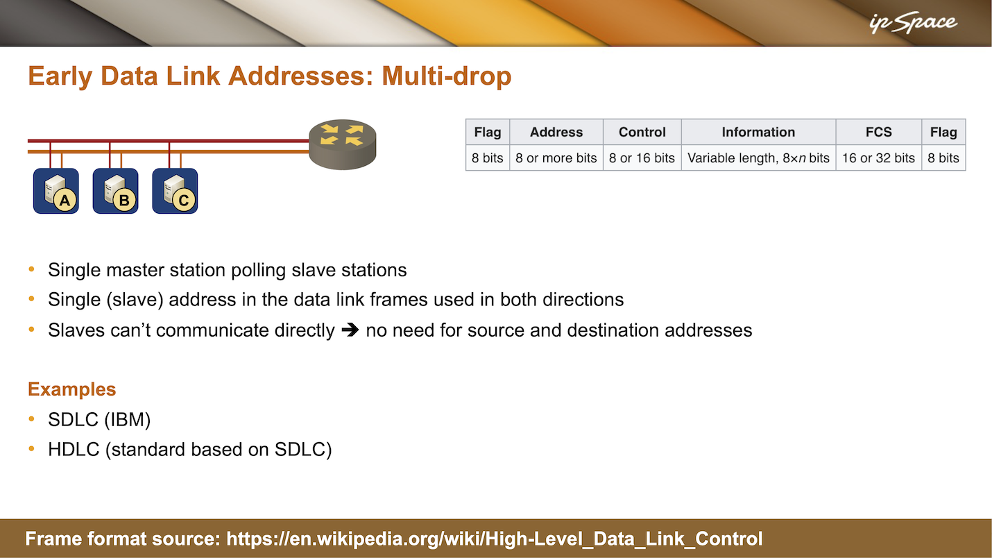
In early multi-drop implementations, a single master would be polling slave stations. Today, we mostly don’t do polling because that is time consuming with very high speeds and with large latencies like satellite communication you can’t afford that anyway. So there are other mechanisms in (for example) wireless or passive optical networks (PON)1 that allocate time slots to different stations so that everyone knows when they can transmit without polling.
Back to ancient stuff: as they figured out that all the communication was going on between a master and a slave, the designers of early protocols decided that they didn’t need two addresses in every data link layer frame because the slaves couldn’t communicate directly anyway.
So what they ended up with is a single address field in the data link layer frame, and it started with 8 bits in SDLC and then got extended to more than 8 bits with HDLC. If the frame is sent by the master, the address is obviously the destination address of the slave, and if the frame is sent by the slave, the address is the source address of the slave sending the frame.
Interestingly, people are still using SDLC and HDLC today2. Most everyone is using some variant of HDLC framing on serial links – the exact same HDLC data link layer format, including the addressing bit, is used for PPP frames. So when you were using PPP encapsulation, there was always the address field and the control byte, which specified whether this was a numbered frame, an unnumbered frame, or a control frame.
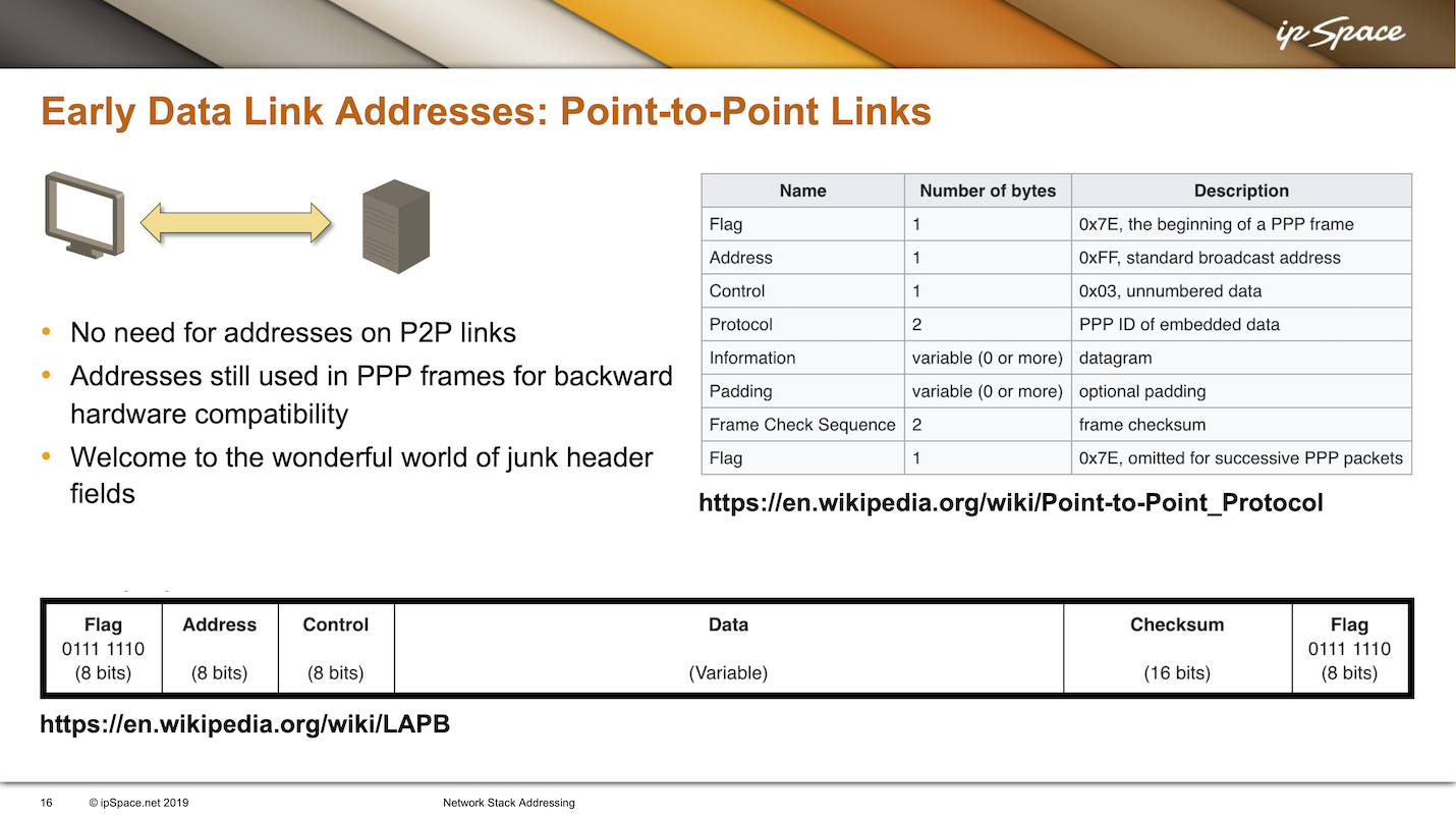
Let’s look at the PPP frame format described in a Wikipedia article:
- Every PPP frame starts with a flag — a sequence of 8 bits that identifies start of frame.
- Then, link in HDLC or SDLC, you have the address bit. As PPP is a point-to-point link between two nodes, it doesn’t have data link layer addresses, so they decided to fake it and put the broadcast address in, meaning “this frame is addressed to everyone on the link that happens to be listening”. Obviously, on a point-to-point link, only the other node is listening, but they had to put something in the address field that makes sense from the protocol perspective.
- Next, they would use the 03 in the control bit, which means unnumbered data frame.
- Finally, you would get the 2-byte protocol ID and then the rest of the PPP frame.
Why are we using so many meaningless header fields in PPP frames? Because there were so many hardware implementations for HDLC or SDLC – the exact same frame format with address and control bytes was also used in LAPB (layer 2 of X25), and LAPD (layer 2 for ISDN signaling).
In those days, everyone was using the same frame format, including the 8-bit address that didn’t mean anything in those days on PPP links. The world of junk header fields didn’t start with VXLAN encapsulating Ethernet frames in IP packets; we had junk header fields in 1980s.
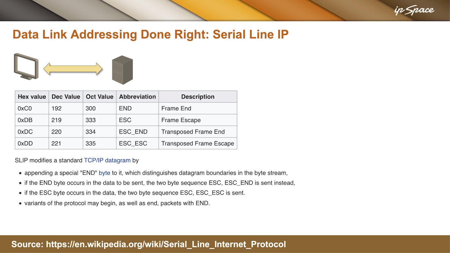
There was another standard that was used less than PPP because it was so awkward, but from the addressing perspective, they got it right. That standard was so-called serial line IP – an extremely simple mechanism for sending IP packets over asynchronous serial links.
On asynchronous serial links, you could only send one 8-byte character at a time with no extra framing like the HDLC start frame. To get around that, SLIP modified TCP/IP datagrams by appending an end byte (decimal value 192) to the end. When receiving an IP datagram, a node would collect characters until you got the end byte and then assume it has collected an IP datagram, and start processing it.
The SLIP approach worked because on a point-to-point serial line you don’t need layer 2 addressing. However, you could only transport IP datagrams with SLIP because it had no usable data link layer. Characters were encoded on the physical layer, the modem provided a string of characters, and as there was no data link layer, you could only transport one network layer protocol on top of that. That was perfectly fine to get people dialing into access servers Internet access, but useless for any enterprise communications because we usually had to deal with more than one layer-3 protocol.
Finally, SLIP designers had to solve another interesting problem: what happens if you have 192 value in the IP header or anywhere in the IP datagram, because the receiving node would interpret that as the end of the datagram. They used a well-known trick called escaping: they would send the escape character and then the original character. Instead of 192, they would send two characters: 219 and 192, or 219 and 220. The next challenge should be obvious: what if there is 219 in the data stream? In that case, they would send 219 and 221.
Long story short: with very simple tricks, SLIP could send IP datagrams over point-to-point links without any data link layer or data link layer addresses.