DHCP Relaying in EVPN VRFs
After figuring out how DHCP relaying works and testing it with VRFs and in VXLAN segments, it seems like a no-brainer to make it work with EVPN.
TL&DR: It works, at least when using Arista vEOS as the relay and Cisco CSR 1000v as the DHCP server.
Lab Topology
We’ll keep using the exact same “physical” topology we used in the VXLAN DHCP relaying lab, add EVPN and BGP to the control-plane cocktail, and put the VXLAN segment into a VRF. We’ll use CSR 1000v as the DHCP server because Cisco IOSv doesn’t support some of the DHCP option-82 sub-options we need.
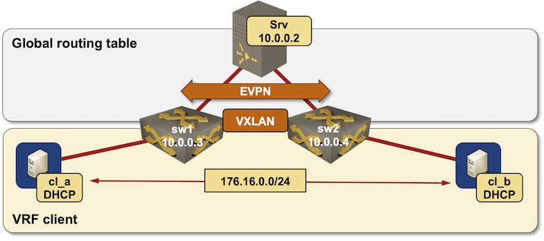
Lab topology diagram
  Interface                  IPv4 address  Description
==============================================================================================
srv (10.0.0.2/32)
  GigabitEthernet2            10.1.0.1/30  srv -> sw1
  GigabitEthernet3            10.1.0.5/30  srv -> sw2

sw1 (10.0.0.3/32)
  Ethernet1                   10.1.0.2/30  sw1 -> srv
  Ethernet2                   10.1.0.9/30  sw1 -> sw2
  Vlan1000                  172.16.0.3/24  VLAN cv1 (1000) -> [cl_a,cl_b,sw2] (VRF: client)

sw2 (10.0.0.4/32)
  Ethernet1                   10.1.0.6/30  sw2 -> srv
  Ethernet2                  10.1.0.10/30  sw2 -> sw1
  Vlan1000                  172.16.0.4/24  VLAN cv1 (1000) -> [cl_a,sw1,cl_b] (VRF: client)

cl_a (10.0.0.5/32)
  GigabitEthernet0/1        172.16.0.5/24  cl_a -> [sw1,cl_b,sw2]

cl_b (10.0.0.6/32)
  GigabitEthernet0/1        172.16.0.6/24  cl_b -> [cl_a,sw1,sw2]
You can view the complete topology file on GitHub.
Device Configurations
I configured VRF-aware DHCP relay (ip dhcp relay information option) on both switches. The DHCP pools on the DHCP server are not VRF-aware due to the Arista EOS bug (misformed sub-option 151). The final device configurations are available in netlab-examples GitHub repository.
ip dhcp relay information option
!
vlan 1000
   name cv1
!
vrf instance client
   rd 65000:1
!
interface Vlan1000
   description VLAN cv1 (1000) -> [cl_a,cl_b,sw2]
   vrf client
   ip address 172.16.0.3/24
   ip helper-address 10.0.0.2 vrf default
   ip ospf area 0.0.0.0
   ip virtual-router address 172.16.0.1/24
!
interface Vxlan1
   vxlan source-interface Loopback0
   vxlan udp-port 4789
   vxlan vlan 1000 vni 101000
!
ip virtual-router mac-address 02:00:ca:fe:00:ff
Does It Work?
Of course, I didn’t expect anything else based on previous test cases. The exchange of DHCP packets is easy to reconstruct from the logs (client, server). As before:
- DHCP client sends a DHCP DISCOVER local broadcast
- The directly connected switch forwards the DHCP request to the DHCP server. The source IP address of the relayed packet, and the giaddr (gateway IP address) in the forwarded DHCP request is the IP address of the outgoing interface (in the global IP routing table).1 The switch also forwards the broadcast Ethernet packet across the VXLAN segment.
- The second switch receives the VXLAN-encapsulated DHCP request broadcast and forwards the second copy of the same packet to the DHCP server.
- DHCP server receives two copies of the DHCP DISCOVER request but replies with a single DHCP OFFER packet to the first DHCP REQUEST packet it received.
- The DHCP server IP address in the DHCP OFFER packet is the relaying switch VRF IP address specified in the server-id-override sub-option.
- The DHCP OFFER packet is sent to the selected relay’s giaddr (global IP address)
- The switch receiving the DHCP OFFER forwards the offer to the DHCP client. The DHCP client thinks the DHCP server IP address is the DHCP relay VRF IP address. Not surprisingly, Client-A uses SW-1 as the DHCP server, and Client-B uses SW-2 as the DHCP server:
cl_a#show dhcp lease
Temp IP addr: 172.16.0.2  for peer on Interface: GigabitEthernet0/1
Temp  sub net mask: 255.255.255.0
   DHCP Lease server: 172.16.0.3, state: 5 Bound
   DHCP transaction id: 2329
   Lease: 86400 secs,  Renewal: 43200 secs,  Rebind: 75600 secs
   Next timer fires after: 11:27:58
   Retry count: 0   Client-ID: cisco-5254.008f.e981-Gi0/1
   Client-ID hex dump: 636973636F2D353235342E303038662E
                       653938312D4769302F31
   Hostname: cl_a
cl_b#show dhcp lease
Temp IP addr: 172.16.0.5  for peer on Interface: GigabitEthernet0/1
Temp  sub net mask: 255.255.255.0
   DHCP Lease server: 172.16.0.4, state: 5 Bound
   DHCP transaction id: 24BB
   Lease: 86400 secs,  Renewal: 43200 secs,  Rebind: 75600 secs
   Next timer fires after: 11:26:31
   Retry count: 0   Client-ID: cisco-5254.0045.41d8-Gi0/1
   Client-ID hex dump: 636973636F2D353235342E303034352E
                       343164382D4769302F31
   Hostname: cl_b
- The DHCP client sends a DHCP REQUEST packet as a local broadcast (it still doesn’t have a confirmed IP address). The DHCP server IP address in the DHCP REQUEST packet is the VRF IP address of the switch that relayed the DHCP OFFER packet.
- Both switches receive the DHCP REQUEST broadcast and relay it to the DHCP server.
- The DHCP server receives two DHCP REQUEST packets and sends two DHCP ACK messages with the DHCP server IP address set to the relay VRF IP address.
- DHCP client receives a DHCP ACK message from the server it sent the request to, but also a second DHCP ACK message from an unknown server. It ignores the second one.
Takeaways:
- The DHCP client thinks one of the directly-connected switches is the DHCP server. That’s the only way to get a DHCP request across VRF boundary.
- When using Arista EOS as the DHCP relay, the DHCP server IP address used by the client is the unicast (not anycast) IPv4 address of the switch.
- Different clients could be using different switches as their “DHCP servers”.
- If the unicast IPv4 address of the relaying switch disappears, the client loses its path to the DHCP server, and cannot extend its lease, but the rebinding process (section 4.4.5 of RFC 2131) should take care of that. With the default settings, the rebinding process starts before 90% of the lease time expires which should be more than enough.
Apart from the minor details listed above, it all looks like a walk in the park, right? It is, and it should work with any DHCP server and any decently-implemented data center switch… as long as you’re using a single DHCP server. More about this juicy detail in the last blog post in this series.
Try It Out!
Want to run this lab on your own, or try it out with different devices? No problem:
- Make sure your preferred device supports inter-VRF DHCP relaying, VXLANs and EVPN.
- Install netlab
- Download the relevant containers or create Vagrant boxes
- Download the EVPN VRF DHCP relaying example into an empty directory
- If you want to use a relaying device that’s not Arista EOS, add a configuration template to
dhcp-relaysubdirectory. - Execute netlab up
- Enjoy! 😊
Next: DHCP Relaying with Redundant DHCP Servers Continue
-
Or an IP address of an interface specified in ip helper address command. On Arista switches, it might be a good idea to use the global loopback interface as the source interface of the forwarded DHCP request. ↩︎