MLAG Deep Dive: System Overview
Multi-Chassis Link Aggregation (MLAG) – the ability to terminate a Port Channel/Link Aggregation Group on multiple switches – is one of the more convoluted1 bridging technologies2. After all, it’s not trivial to persuade two boxes to behave like one and handle the myriad corner cases correctly.
In this series of deep dive blog posts, we’ll explore the intricacies of MLAG, starting with the data plane considerations and the control plane requirements resulting from the data plane quirks. If you wonder why we need all that complexity, remember that Ethernet networks still try to emulate the ancient thick yellow cable that could lose some packets but could never reorder packets or deliver duplicate packets.
To make matters worse, some applications running directly on top of Ethernet3 would abruptly drop their sessions when faced with a single reordered or duplicated packet4, making IEEE extremely cautious. In recent years, they relaxed a bit – the 802.1AX-2020 standard claims to provide “low risk of duplication or misordering” – but it’s still bad form to mess things up. Who knows, even a UDP-based application without application-level sequence numbers 5 could get confused.
Throughout the series, we’ll use a simple topology with two switches in an MLAG cluster and three types of nodes attached to them:
- Hosts with a single uplink connected to one of the switches – X and Y
- Hosts connected to both switches with a link aggregation group (LAG) – A and B
- Host with a failed LAG member – C
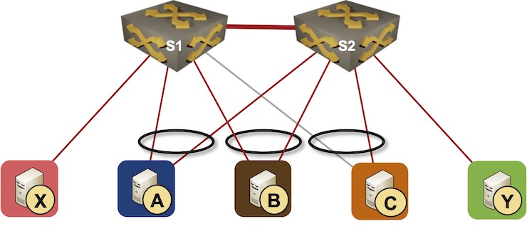
Simple MLAG topology
The nodes that have functioning links with a single member of an MLAG cluster are sometimes called orphan nodes. We’ll use that term regardless of whether the node is using LACP or not – the orphan nodes in our topology are X, Y, and C (because the link between S1 and C is down).
MLAG members need a data-plane path between them to forward frames between orphan nodes (example: between X and Y). Standalone MLAG implementations usually use a dedicated peer link. Some implementations use the network core (fabric) to exchange data between MLAG members; we’ll dive into the complexities of replacing a peer link with a fabric interconnect in a future blog post.
Peer Link Failure
Implementations using a peer link cannot live without it6; it’s crucial to make the peer link as reliable as possible. Most design guides tell you to use multiple parallel links in a LAG (because we’re in a bridged world) connected to multiple linecards if you use a chassis switch.
Even then, what should we do if a peer link fails? The minority part of the cluster has to remove directly connected LAG member links from the link aggregation groups7, and the easiest way to do that is to shut them down.
The “shut down the LAG members” approach might have unintended consequences. In our scenario, if S2 decides it has to do that, C gets disconnected from the network. Unfortunately, we can do nothing about that.
Smarter MLAG implementations (example: Cumulus Linux) try to recover from the disaster if they are reasonably sure that the primary MLAG member might have failed. In that case, the secondary MLAG member has to:
- Drop from the cluster
- Stop using cluster-wide LACP system ID and system MAC address
- Revert to the local LACP system ID and system MAC address.
- Restart LACP sessions using a different system ID hoping that the remote nodes don’t get confused.
Properly implemented remote nodes would renegotiate LACP session with the standalone former member of the MLAG cluster if they lost contact with the primary MLAG member, or reject the attempt to renegotiate the LACP session if the primary MLAG member is still operational (and we experienced network partitioning).
Finally, how do you decide which part of a two-node cluster is in the minority? Welcome to the Never Take Two Chronometers to the Sea land. MLAG implementations go to great lengths trying to figure out whether the other cluster member failed (in which case the LAG members should remain active) or whether the other node is still active, but not reachable over the failed peer link.
Using BFD across fabric uplinks is pretty common and does not depend on assistance of third-party devices8. Some implementations also try to reach the other MLAG member over the attached LAGs. This can only work if the remote device is willing to resend the probe onto another LAG member through its control plane – an IEEE bridge is not supposed to forward a packet to a link through which it has been received, and the whole LAG is treated as a single link. There is no standard way to send probes through LAG-attached clients; vendors supporting this functionality have developed incompatible proprietary solutions.
In our topology, S1 and S2 cannot use BFD as they don’t have fabric uplinks. They could try to send probes through A and B, but that would only work if A and B assisted them, which means that S1, S2, A, and B would have to be switches from the same vendor.
Basic Control Plane Setup
Before discussing the data-plane details, we have to get working link aggregation groups between S1/S2 and A, B, and C. S1 and S2 have to pretend they’re a single device – they must use the same LACP system ID and the same system MAC address9. To get that done, we need a control-plane protocol that will:
- Verify that the other switches10 in the MLAG cluster work as expected.
- Agree on the IEEE bridge and LACP parameters (system ID, system priority, and port priority) with the other cluster members. Multi-Chassis LACP (mLACP) Application Procedures part of RFC 7275 (ICCP) describes a sample implementation.
- Exchange port/LAG state between MLAG cluster members to identify orphan nodes.
ICCP is a control-plane protocol that does all of the above, but we might need more. We’ll discover the additional control-plane features needed in an MLAG cluster while figuring out how to make layer-2 and layer-3 forwarding work.
Next: Dynamic MAC Learning Continue
Revision History
- 2022-06-01
- Updated the what can secondary switch do after peer link failure part of the blog post based on feedback by Erik Auerswald. Also added a few more details on peer failure detection.
-
At least it was until we got EVPN ;) ↩︎
-
Packet forwarding process lovingly called switching by vendor marketers ↩︎
-
Without using a network-layer protocol like IP ↩︎
-
IBM SNA running on LAN media was notoriously prickly ↩︎
-
Because we all know that the network is reliable and never messes things up, right? ↩︎
-
More about that when we get to the data-plane details ↩︎
-
Anything else could result in weird forwarding behavior; the proof is left as an exercise for the reader. Keep in mind that the end-hosts with a single uplink (LAG is a single uplink) are often not running STP. ↩︎
-
Apart from the obvious need to have IP- or MAC-level forwarding ;) ↩︎
-
IEEE bridges don’t have interface MAC addresses. They use a single system-wide MAC address. ↩︎
-
Some implementations support more than two switches in an MLAG cluster ↩︎
Regarding "It could also try to restart LACP using a different system ID hoping that the remote nodes don’t get confused, but I have yet to see an implementation that would go that far."
The Cumulus Linux MLAG implementation is documented to do this in some peer link failure scenarios:
Thank you! Updated the blog post.