… updated on Monday, July 12, 2021 18:00 UTC
Unnumbered Ethernet Interfaces, DHCP Edition
Last week we explored the basics of unnumbered IPv4 Ethernet interfaces, and how you could use them to save IPv4 address space in routed access networks. I also mentioned that you could simplify the head-end router configuration if you’re using DHCP instead of per-host static routes.
Obviously you’d need a smart DHCP server/relay implementation to make this work. Simplistic local DHCP server would allocate an IP address to a client requesting one, send a response and move on. Likewise, a DHCP relay would forward a DHCP request to a remote DHCP server (adding enough information to allow the DHCP server to select the desired DHCP pool) and forward its response to the client.
What we need to make unnumbered IPv4 Ethernet interfaces work with DHCP is an extra step: as a DHCP reply (locally originated or relayed) is sent to a client connected over an unnumbered IPv4 interface, a static host route is added to the router’s routing table to make that client reachable through the router.
I’ve first seen static routes created from DHCP responses in DHCPv6 relays supporting IPv6 prefix delegation with IA_PD option. A few years later, DHCPv6 relays started adding host routes based on IA_NA (address allocation) responses. Similar behavior is now available in some IPv4 DHCP implementations1.
Does It Really Work?
A lab test always beats academic discussions, and we already have the lab built. We’ll use the same lab setup as the last time with a slightly different IP addressing. Instead of static IP addresses and static routes, we’ll configure DHCP server on the access router, and use DHCP-based address allocation on the clients.
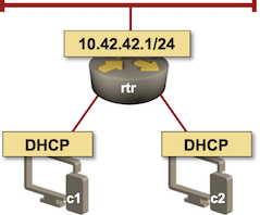
Lab topology
To make our setup work we have to configure DHCP client on c1 and c2. I used Cisco IOS XE for the clients; I could have used Linux VMs or containers, but then I’d have to figure out how to configure DHCP client on a Linux box. Call me lazy…
interface GigabitEthernet2
 description c1 -> rtr [dhcp]
 ip address dhcp
On the access router we have to configure:
- A DHCP pool;
- A loopback interface with an IP prefix exactly matching the DHCP pool IP prefix;
- Unnumbered access interfaces.
interface Loopback1
 ip address 10.42.42.1 255.255.255.0
!
ip dhcp pool Access
 network 10.42.42.1 255.255.255.0
 default-router 10.42.42.1
!
interface GigabitEthernet2
 no ip address
 ip unnumbered Loopback1
interface GigabitEthernet3
 no ip address
 ip unnumbered Loopback1
After a few seconds, we’ll see the DHCP bindings2:
rtr#show ip dhcp binding
Bindings from all pools not associated with VRF:
IP address      Client-ID/ 		Lease expiration 	Interface
		Hardware address/
		User name
10.42.42.2      0063.6973.636f.2d35.    Jun 07 2021 07:27 AM    GigabitEthernet3
                3235.342e.3030.3438.
                2e32.6462.362d.4769.
                32
10.42.42.3      0063.6973.636f.2d35.    Jun 07 2021 07:27 AM    GigabitEthernet2
                3235.342e.3030.6333.
                2e61.3066.382d.4769.
                32
At the same time, the static host routes pointing to allocated DHCP addresses are added to the IP routing table:
rtr#show ip route 10.42.42.0 longer-prefixes | begin Gateway
Gateway of last resort is 192.168.121.1 to network 0.0.0.0

      10.0.0.0/8 is variably subnetted, 5 subnets, 2 masks
C        10.0.0.3/32 is directly connected, Loopback0
C        10.42.42.0/24 is directly connected, Loopback1
L        10.42.42.1/32 is directly connected, Loopback1
S        10.42.42.2/32 is directly connected, GigabitEthernet3
S        10.42.42.3/32 is directly connected, GigabitEthernet2
From last week’s blog post we know that’s enough to make the IP routing work – we can ping c2 (10.42.42.2) and the other loopback interface of rtr (10.0.0.3) from c1.
c1#ping 10.42.42.2
Type escape sequence to abort.
Sending 5, 100-byte ICMP Echos to 10.42.42.2, timeout is 2 seconds:
..!!!
Success rate is 60 percent (3/5), round-trip min/avg/max = 1/1/2 ms
c1#ping 10.0.0.1
Type escape sequence to abort.
Sending 5, 100-byte ICMP Echos to 10.0.0.1, timeout is 2 seconds:
!!!!!
Success rate is 100 percent (5/5), round-trip min/avg/max = 1/1/1 ms
Next: Running OSPF over Unnumbered Ethernet Interfaces Continue
Repeatability Matters
Want to check my lab results? The final router configurations are on GitHub.
Want to build a lab in a few minutes and have it configured in seconds? You’ll have to invest a bit of time first:
- Install Vagrant and libvirt. If you’re running your lab on Windows or MacOS host, use a Ubuntu virtual machine.
- Build CSR 1000v box
- Install netlab
After you got everything up and running:
- Copy my lab topology into dhcp.yml in an empty directory (or clone my netlab-examples repository)
- Execute netlab create dhcp.yml to create Vagrantfile, Ansible inventory and Ansible configuration file
- Execute vagrant up to start the lab
- Execute netlab initial to configure the devices.
You could apply the configuration changes outlined in this blog post manually. I decided to automate them:
- Add client-side and server-side Jinja2 templates to your directory
- Execute netlab config dhcp-server.j2 -l rtr3 to configure the DHCP server
- Execute netlab config dhcp-client.j2 -l c1,c2 to configure DHCP clients
- Use netlab connect to connect to the routers and inspect the results.
Revision History
- 2021-07-12
- Updated the blog post to use the new netlab CLI.
-
At least in IOS XE release 16.6, pointers to other implementations are most welcome – please write a comment. ↩︎
-
I removed the type and state columns from the printout to squeeze it into available width. ↩︎
-
netlab config command invokes an Ansible playbook and accepts the usual ansible-playbook parameters. The -l parameter limits the playbook run to a subset of devices. ↩︎
Just read your blog post about Azure Networking 101. I guess their Azure router and DHCP setup may look very similar to this, right?
@Hoang: The data plane is similar to what I described, the control plane is different:
Thanks Ivan. FYI, Juniper has this feature (installing access route) enabled by default. I used to be surprised by a bunch of these /32 routes on my router, and had to turn it off.
https://www.juniper.net/documentation/us/en/software/junos/dhcp/topics/topic-map/dhcp-access-supressing.html
This kind of setup also eliminates many Layer-2 attacks like ARP spoofing, DHCP spoofing, right? Have you seen any enterprises using this in production?
The setup we're discussing here would be most useful in access networks (example: campus). In data centers you're usually faced with a dumb L2 switch in the hypervisor, and it makes little sense trying to fix the damage at the next hop (ToR switch).
Unfortunately I haven't been working with campus networks for ages, so I can't tell you what's happening out there.
So for the pings from c1 to c2 to work, rtr is performing proxy ARP, correct? Could you share ARP tables from router and clients?
@Anonymous: Yes, rtr is performing proxy ARP.
Based on that you should be able to figure out the details of the ARP tables, or you could set up a lab using my configs (or even just my lab setup instructions) and see the details for yourself.
Is it a typo or why is the "network" statement in the DHCP pool config set to 10.42.42.1 255.255.255.0 instead of 10.42.42.0 255.255.255.0 ?
@Florian: Call it a "somewhat suboptimal configuration template" ;)
IOS ignores the host portion of the IP prefix specified in the network statement, so it all works as configured.