… updated on Sunday, May 8, 2022 09:21 UTC
Multi-Chassis Link Aggregation (MLAG) Basics
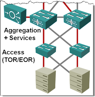
If you ask any networking engineer building layer-2 fabrics the traditional way about his worst pains, I’m positive Spanning Tree Protocol (STP) will be very high on the shortlist. In a well-designed fully redundant hierarchical bridged network where every device connects to at least two devices higher in the hierarchy, you lose half the bandwidth to STP loop prevention whims.

You REALLY SHOULD not build layer-2 data center fabrics with spanning tree anymore1, but if you’re still stuck in STP land, you can try to dance around the problem:
- Push routing as close to the network edge as you can. This works if your environment already uses overlay virtual networking (for example, VMware NSX or Docker/Kubernetes), otherwise you might get a violent kickback from the server admins when they realize they cannot move the VMs at will anymore;
- Play with per-VLAN costs in PVST+ or MSTP, ensuring the need for constant supervision and magnificent job security;
Considering the alternatives, multi-chassis link aggregation just might be what you need.
Link Aggregation Basics
Link aggregation is an ancient technology that allows you to bond multiple parallel links into a single virtual link (link aggregation group – LAG). With parallel links being replaced by a single virtual link, STP detects no loops and all the physical links can be fully utilized.

I was also told that link aggregation makes your bridged network more stable2. Every link state change triggers a Topology Change Notification in spanning tree, potentially sending a large part of your network through the STP listening-learning-forwarding state diagram. A link failure of a LAG member does not change the state of the aggregation group (unless it was the last working link in the group), and since STP rides on top of aggregated interfaces, it does not react to the failure.
Multi-Chassis Link Aggregation
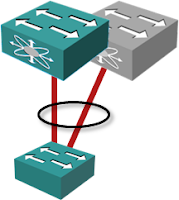
Imagine you could pretend two physical boxes use a single control plane and coordinated switching fabrics. The links terminated on two physical boxes would seem to terminate within the same control plane and you could aggregate them using LACP. Welcome to the wonderful world of Multi-Chassis Link Aggregation (MLAG).

MLAG nicely solves two problems:
- When used in the network core, multiple links appear as a single link. No bandwidth is wasted due to STP loop prevention while you still retain almost full redundancy – just make sure you always read the smallprint to understand what happens when one of the two switches in the MLAG pair fails.
- When used between a server and a pair of top-of-rack switches, it allows the server to use the full aggregate bandwidth while still retaining resiliency against a link or switch failure.
Standardization? Not Really
MLAG could be a highly desirable tool in your design/deployment toolbox, but few vendors have taken the pains to start the standardization effort, the notable exception being Juniper with ICCP (RFC 7275). EVPN is also supposed to be able to solve most of the MLAG control-plane challenges, but it’s questionable whether the resulting complexity is worth the effort.
Architectural Approaches
If you want to make two (or more) devices act like a single device, you have to build some sort of a clustering solution. Doing it from scratch shouldn’t be too hard, but when you have to bolt this functionality on top of a decade-old heap of real-time kludges3 the challenges become interesting.
The architectural approaches used by individual vendors are widely different:
- A common early approach was to turn all but one of the control planes of MLAG cluster members into half-comatose state. Cisco VSS could do that with two devices, Juniper (Virtual Chassis) or HP (IRF) reused their stackable switch technologies.
- Modern implementations use cooperative control planes (Cisco vPC, Arista or Cumulus MLAG)
- Centralized control plane was also a popular solution in the heydays of orthodox SDN.
More information
You’ll get a high-level overview of network virtualization, LAN reference architectures, multi-chassis link aggregation, port extenders and large-scale bridging in Data Center 3.0 for Networking Engineers webinar.
Revision History
- 2022-05-08
- Significant rewrite, removing references to old technologies and obsolete marketing gimmicks, and added a brief mention of ICCP and EVPN.
-
You should also forget about the “wonderful” proprietary fabric technologies promised by the networking vendors during the early 2010s. ↩︎
-
Considering we’re discussing bridged fabrics, I should probably say less unstable. ↩︎
-
Called Network Operating System because marketing ↩︎

The concept is easy to sell to management and it works very well - until something goes wrong that is - then all hell breaks loose. As you rightly said "understand what happens if the switch hosting the control plane fails" or even a downstream switch for that matter. A number of years ago I rolled it out on a large campus and, a few catastrophic failures later, remove it all.
Maybe I am a curmudgeon. I'd like to think that it's just healthy paranoia. :)
I feel that someone needs to go to bat for Nortel / Avaya, since they were doing SMLT way before Cisco's VSS came out to play.
http://www.trcnetworks.com/nortel/Data/Swiches/8600/pdfs/Split_multi_Link_Trunking.pdf
...and a highlight:
"Spanning Tree Protocol is disabled on the SMLT ports"
Not relying on STP for redundancy is one thing. Switching it off is a whole other thing. Deploy SMLT and hope that nobody ever loops two edge switches? No thanks.
Nortel has an extra twist: R(outed)SMLT, which is kind of like VPC + HSRP. Except there's no virtual router IP. Give your routers x.x.x.1 and x.x.x.2. Configure .1 as the gateway on end systems. If .1 fails, .2 assumes the dead router's address.
If there's a power outage, and only .2 boots back up? You're done. (though there's a write-status-to-nvram fix for this)
Come to think of it, it's a lot like vPC in that regard!
Basic deployment scenarios:
http://www116.nortel.com/docs/bvdoc/ene_tech_pubs/SMLT_and_RSMLT_Deployment_Guide_V1.1.pdf
Campus design guide (outlines link aggregation and loop detection deployment):
http://www142.nortelnetworks.com/mdfs_app/enterprise/TCGs/pdf/NN48500-575_2.0_Large_Campus_TSG.pdf
Configuration Guide for SMLT (includes some of the better technical information):
http://www142.nortelnetworks.com/mdfs_app/enterprise/ers8600/5.1/pdf/NN46205-518_02.01_Configuration-Link-Aggregation.pdf
Configuration Guide for RSMLT (both chassis share layer 3 information like OSPF/BGP state)
http://www142.nortelnetworks.com/mdfs_app/enterprise/ers8600/5.1/pdf/NN46205-523_02.02_Configuration_IP_Routing.pdf
http://h3c.com/portal/Technical_Support___Documents/Technical_Documents/
for all equipmen, then move to each swicth model if needed - seems IRF is supported on many models - 12k, 9500E, 7500E,58xx's. Could not see if IRF between different models is possible.
Fairly thin on
http://h3c.com/portal/Products___Solutions/Technology/IRF/
One of config guides can be found on
http://h3c.com/portal/download.do?id=1038276
There seem to be no restriction on STP, in fact it seems this supports even MPLS and many other features.. I haven't had a chance to lay my hands on any of these products, above is only by reading documents :-)
There was a prolonged marketing guy catfight @ networkworld between cisco's VSS and nortel SMLT/RSMLT.
Thanks!
STP loop prevention turns off (sets them to "blocking") half of the links in a dual-tree design displayed in the first diagram (blocked links are grayed out in the diagram). STP itself uses very little bandwidth.
http://blog.ioshints.info/2010/09/vmotion-elephant-in-data-center-room.html
Cisco VSS is the way of the future as it will do away with STP. ;)
BTW, VSS is just stacking-on-steroids; I prefer vPC.
1) Simple Loop Protection Protocol - SMLT switches send probes down their SMLT links to the closet switch. If you see the SLPP hello packet return on another interface you know that you have a loop condition
2) Control Plane limiting for Broadcast / Multicast traffic can be configured on a per port basis. I configure it on my SMLT links to down the interface and/or VLAN that is sending excess broadcast or multicast traffic
In both solutions, this is configured on both SMLT switches with the trigger thresholds set to different levels (5 SLPP hello probes vs 50) so that only one side of the SMLT should be disabled during a downstream loop.
Chassis (12500, 9500, 7500): Currently up to 2 devices can be clustered. Rumor is that will be increased to 4 in the future.
5820: Up to 9 devices can be clustered
5800, 5500, 5120: Up to 8 devices can be clustered
Certain mixed devices can be clustered using IRF, specifically 5820's and 5800's.
IRF Clustering is fully stateful, and supports basically all the regular switch featuresets. With regards to STP, an environment that uses all IRF on the Core or Aggregation devices can remove STP from the environment, and use LACP to provide path redundancy instead.
I believe that the MSR routers support IRF as well, but I haven't configured it myself.