… updated on Sunday, September 28, 2025 11:23 +0200
EVPN Designs: Layer-3 Inter-AS Option A
A netlab user wanted to explore a multi-site design where every site runs an independent EVPN fabric, and the inter-site link is either a layer-2 or a layer-3 interconnect (DCI). Let’s start with the easiest scenario: a layer-3 DCI with a separate (virtual) link for every tenant (in the MPLS/VPN world, we’d call that Inter-AS Option A)
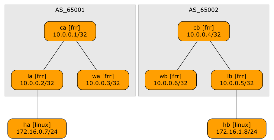
Lab topology
- The switches within a single site run OSPF, IBGP (full mesh), and EVPN.
- The link between the sites belongs to a tenant VRF. You could also use a VLAN trunk in which every VLAN belongs to a different tenant VRF.
- WAN edge routers (WA, WB) have a separate EBGP session in every tenant VRF. The routes exchanged over that session are propagated over intra-site EVPN as type-5 routes.
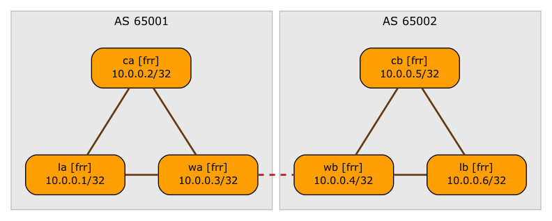
BGP sessions (VRF sessions are shown as dashed lines)
Here’s the netlab topology we’ll use to create this design (as always, it’s available on GitHub).
module: [ ospf, bgp, vxlan, vlan, vrf, evpn ]provider: clabdefaults.device: frrgroups:_auto_create: Truesite_a: # Site A - core, leaf, wan edgemembers: [ la, ca, wa ]bgp.as: 65001site_b:members: [ wb, cb, lb ] # Site B - core, leaf, wan edgebgp.as: 65002hosts:members: [ ha, hb ] # Hosts attached to leaf-A and leaf-Bdevice: linuxvrfs:tenant:links: [ wa-wb ] # Inter-AS VRF link (inter-AS option A)evpn.transit_vni: True # Symmetric IRB in Site-A and Site-Bvlans:tenant_a: # VLAN in Site Avrf: tenant # ... part of tenant VRFlinks: [ la-ha ] # ... with HA being part of the VLANtenant_b: # VLAN in site Bvrf: tenant # ... part of tenant VRFlinks: [ lb-hb ] # ... with HB being part of the VLANlinks: # Intra-site fabrics- group: site_a # Site A (core-to-leaf, core-to-WAN edge)members: [ ca-la, ca-wa ]- group: site_b # Site B (core-to-leaf, core-to-WAN edge)members: [ cb-lb, cb-wb ]
- The nodes in the lab topology belong to three groups: switches in site A (lines 8-10), switches in site B (lines 11-13), and hosts attached to the switches (lines 14-16).
- We have a single tenant. It has one VLAN in site A (lines 24-26), another VLAN in site B (lines 27-29), and a VRF link between the sites (line 20).
- We use EVPN symmetric IRB for the tenant (line 21).
- Finally, we need core links within each site (lines 31-35)
Let’s see how the tenant EVPN routes are propagated across the two sites. Here’s the EVPN BGP table on the WAN edge router of Site-A:
wa# show bgp evpn route
BGP table version is 4, local router ID is 10.0.0.3
Status codes: s suppressed, d damped, h history, * valid, > best, i - internal
Origin codes: i - IGP, e - EGP, ? - incomplete
EVPN type-1 prefix: [1]:[EthTag]:[ESI]:[IPlen]:[VTEP-IP]:[Frag-id]
EVPN type-2 prefix: [2]:[EthTag]:[MAClen]:[MAC]:[IPlen]:[IP]
EVPN type-3 prefix: [3]:[EthTag]:[IPlen]:[OrigIP]
EVPN type-4 prefix: [4]:[ESI]:[IPlen]:[OrigIP]
EVPN type-5 prefix: [5]:[EthTag]:[IPlen]:[IP]

   Network          Next Hop            Metric LocPrf Weight Path
                    Extended Community
Route Distinguisher: 65000:1
 *>i [5]:[0]:[24]:[172.16.0.0]
                    10.0.0.1(la)             0    100      0 ?
                    RT:65000:1 ET:8 Rmac:b6:c1:dc:de:ea:9b
 *>  [5]:[0]:[24]:[172.16.1.0]
                    10.0.0.3(wa)                           0 65002 ?
                    ET:8 RT:65000:1 Rmac:72:8e:c8:29:ff:55
 *>  [5]:[0]:[30]:[10.1.0.16]
                    10.0.0.3(wa)             0         32768 ?
                    ET:8 RT:65000:1 Rmac:72:8e:c8:29:ff:55
 *>  [5]:[0]:[32]:[172.16.1.6]
                    10.0.0.3(wa)                           0 65002 i
                    ET:8 RT:65000:1 Rmac:72:8e:c8:29:ff:55
Route Distinguisher: 10.0.0.1:1000
 *>i [2]:[0]:[48]:[ca:f4:00:01:00:00]:[32]:[172.16.0.1]
                    10.0.0.1(la)                  100      0 i
                    RT:65000:1 RT:65000:1000 ET:8 Rmac:b6:c1:dc:de:ea:9b
 *>i [2]:[0]:[48]:[ca:f4:00:01:00:00]:[128]:[fe80::c8f4:ff:fe01:0]
                    10.0.0.1(la)                  100      0 i
                    RT:65000:1000 ET:8
 *>i [3]:[0]:[32]:[10.0.0.1]
                    10.0.0.1(la)                  100      0 i
                    RT:65000:1000 ET:8

Displayed 7 prefixes (7 paths)
- The leaf switch (LA) is advertising two type-2 routes (its VLAN IP address, 172.16.0.2, and the HA MAC address), and a type-3 route (used to build the ingress replication tree).
- WA has four type-5 (IP prefix) routes: the VLAN prefix advertised by LA, and three routes advertised by WA.
Let’s inspect the VRF routing table on WA to see where those other three routes are coming from:
wa# show ip route vrf tenant
Codes: K - kernel route, C - connected, L - local, S - static,
       R - RIP, O - OSPF, I - IS-IS, B - BGP, E - EIGRP, N - NHRP,
       T - Table, v - VNC, V - VNC-Direct, A - Babel, F - PBR,
       f - OpenFabric, t - Table-Direct,
       > - selected route, * - FIB route, q - queued, r - rejected, b - backup
       t - trapped, o - offload failure

IPv4 unicast VRF tenant:
C>* 10.1.0.16/30 is directly connected, eth2, weight 1, 00:00:50
L>* 10.1.0.17/32 is directly connected, eth2, weight 1, 00:00:50
B>* 172.16.0.0/24 [200/0] via 10.0.0.1, tvni-100 onlink, weight 1, 00:00:37
B>* 172.16.0.1/32 [200/0] via 10.0.0.1, tvni-100 onlink, weight 1, 00:00:37
B>* 172.16.1.0/24 [20/0] via 10.1.0.18, eth2, weight 1, 00:00:37
B>* 172.16.1.6/32 [20/0] via 10.1.0.18, eth2, weight 1, 00:00:37
One of the three routes advertised into EVPN as type-5 routes by WA is the directly connected prefix (WA-WB) redistributed into BGP; the other two are BGP routes. Let’s see where they came from:
wa# show ip bgp vrf tenant
BGP table version is 5, local router ID is 10.0.0.3, vrf id 4
Default local pref 100, local AS 65001
Status codes:  s suppressed, d damped, h history, u unsorted, * valid, > best, = multipath,
               i internal, r RIB-failure, S Stale, R Removed
Nexthop codes: @NNN nexthop's vrf id, < announce-nh-self
Origin codes:  i - IGP, e - EGP, ? - incomplete
RPKI validation codes: V valid, I invalid, N Not found

     Network          Next Hop            Metric LocPrf Weight Path
 *>  10.1.0.16/30     0.0.0.0(wa)              0         32768 ?
 *                    10.1.0.18(wb)            0             0 65002 ?
 *>i 172.16.0.0/24    10.0.0.1(la)<            0    100      0 ?
 *>i 172.16.0.1/32    10.0.0.1(la)<                 100      0 i
 *>  172.16.1.0/24    10.1.0.18(wb)                          0 65002 ?
 *>  172.16.1.6/32    10.1.0.18(wb)                          0 65002 i
The other two routes advertised by WA were received over the tenant (VRF) EBGP session from WB. Likewise, WA created VRF BGP routes from EVPN routes advertised by LA, and is propagating them to WB.
These are thus the steps needed to propagate the routing information from LA to LB:
- LA advertises the VLAN-A prefix as a type-5 EVPN route. It also advertises its VLAN IP address in a type-2 EVPN route, and might advertise the HA IP address after HA sends the first ARP request.
- WA is converting the EVPN routes into IPv4 BGP routes and inserting them in the VRF BGP table.
- The VRF IPv4 BGP routes are sent to WB.
- WB receives the IPv4 EBGP routes from WA and inserts them into the VRF BGP table.
- WB selects the best VRF BGP routes, converts them into EVPN type-5 routes, and sends them to LB.
- LB uses the type-5 EVPN routes to build the tenant forwarding table.
Don’t trust me? Build the lab and explore. I’ll just give you the final result (VRF routing table on LB)1:
lb# show ip route vrf tenant
Codes: K - kernel route, C - connected, L - local, S - static,
       R - RIP, O - OSPF, I - IS-IS, B - BGP, E - EIGRP, N - NHRP,
       T - Table, v - VNC, V - VNC-Direct, A - Babel, F - PBR,
       f - OpenFabric, t - Table-Direct,
       > - selected route, * - FIB route, q - queued, r - rejected, b - backup
       t - trapped, o - offload failure

IPv4 unicast VRF tenant:
B>* 10.1.0.16/30 [200/0] via 10.0.0.4, tvni-100 onlink, weight 1, 00:02:13
B>* 172.16.0.0/24 [200/0] via 10.0.0.4, tvni-100 onlink, weight 1, 00:02:12
B>* 172.16.0.1/32 [200/0] via 10.0.0.4, tvni-100 onlink, weight 1, 00:02:12
C>* 172.16.1.0/24 is directly connected, vlan1001, weight 1, 00:02:26
L>* 172.16.1.6/32 is directly connected, vlan1001, weight 1, 00:02:26
Replication Is Crucial
Want to explore the EVPN behavior of your favorite devices? It’s trivial:
- Set up a netlab environment (example, installation guide, using GitHub Codespaces with Arista cEOS containers)
- Download the lab topology file into an empty directory or use
netlab up https://github.com/ipspace/netlab-examples/blob/master/EVPN/inter-as-a/topology.yml(more details) - Execute
netlab up, optionally adding-d _your_device_and-p _provider_. The lab topology uses FRRouting containers; to use Arista EOS containers, use-d eos, to use Aruba AOS-CX VMs, use-d arubacx -p libvirt(more options).
Revision History
- 2025-09-28
- The changed order of nodes in the lab topology (needed to generate nice-looking graphs without tweaking the
graph.dotfile) resulted in changed IP addresses and router IDs. - Add a diagram of BGP sessions
- Add the “netlab up with URL” command
- The changed order of nodes in the lab topology (needed to generate nice-looking graphs without tweaking the
-
Please note that the routing table printout was taken after HA started pinging HB, prompting LA to advertise the HA IP address, which WA converted into a 172.16.0.7/32 BGP prefix. ↩︎