Hub-and-Spoke VPN Topology
Hub-and-spoke topology is by far the most complex topology I’ve ever encountered in the MPLS/VPN (and now EVPN) world. It’s used when you want to push all the traffic between sites attached to a VPN (spokes) through a central site (hub), for example, when using a central firewall.

You get the following diagram when you model the traffic flow requirements with VRFs. The forward traffic uses light yellow arrows, and the return traffic uses dark orange ones.
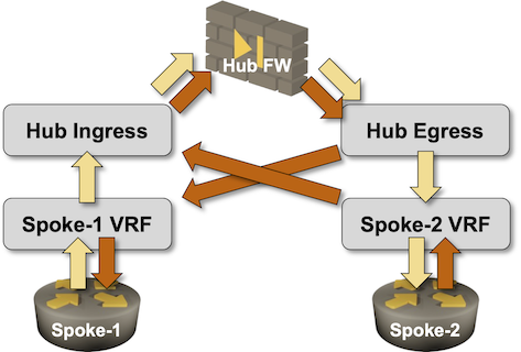
Notes:
- In a generic scenario, you need an ingress and an egress firewall interface for routing purposes. Please note that these are not inside and outside interfaces, as all traffic enters through the ingress interface and leaves through the egress interface.
- From the firewall perspective, you could use a one-arm design where all the traffic enters and exists the firewall through the same interface. Getting that to work on the adjacent routers (a router is hiding behind every VRF box) requires interesting tricks like Policy-Based Routing. I might cover them in another blog post.
- Trying to get stateful firewall traffic inspection to work in scenarios where all traffic (including the return traffic) enters through one interface and exists through another interface is an interesting exercise in futility.
- Each spoke site has to be connected to a different VRF. Two sites connected to the same VRF could communicate directly.
TL&DR: Just because you could does not mean that you should. You’ve been warned.
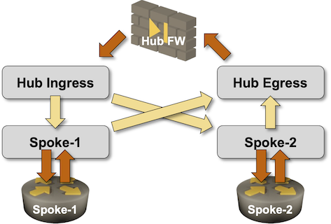
Still here? Let’s move to the next bit of the puzzle: routing. The traffic in a network always flows in the opposite direction of the route propagation1, which means that the route propagation in our design should go:
- From the spoke VRFs to egress VRF
- Through the firewall into the ingress VRF2
- Finally, from the ingress VRF into the spoke VRFs.
The dark orange arrows in the following diagram are routing protocol updates; the light yellow ones are route leaks between VRFs3.
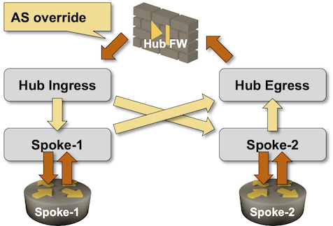
The final piece of the puzzle: the routing protocols. We’re assuming that the route leaking between VRFs uses some unspecified mechanism (usually involving BGP) and that the leaked routes get redistributed into the PE-CE routing protocol.
- RIP would work just fine.
- OSPFv2/OSPFv3 would have no problem as long as the OSPF instances running in the Hub Ingress and the Hub Egress VRFs use different OSPF router IDs4.
- BGP would work, but as the AS number of the router behind the Hub Ingress VRF is probably the same as the AS number of the router behind the Hub Egress VRF, you’d have to bypass the BGP AS-path loop prevention logic. You could, for example, use AS override on the firewall.
Next: Hub-and-Spoke VPN on a Single PE-Router Continue
-
If you wonder why that’s the case, please stop reading and watch the networking fundamentals videos first. ↩︎
-
We’ll assume that the firewall is also a decent router that can be used as the CE router running OSPF or BGP. ↩︎
-
We could do route leaking on a single PE device or in an MPLS/VPN or EVPN network. ↩︎
-
Now you know why you can configure OSPF router ID of individual VRF instances on most network devices. ↩︎
We actually do this at scale, while accounting for several tiers of failover, and purely in BGP (no PBR at all). Definitely not for the faint of heart. I wrote a blog last year about how we solved this “problem” in case you’re interested.
https://www.sms.com/blog/complex-routing-symmetry-in-bgp/
website returns "403 Forbidden"
Are you in the US? Link should work… but it’s plausible that there are country blocks in place given our primary customer.