DHCP Relaying with Redundant DHCP Servers
Previous posts in this series (DHCP relaying principles, inter-VRFs relaying, relaying in VXLAN segments and relaying from EVPN VRF) used a single DHCP server. It’s time to add another layer of complexity: redundant DHCP servers.
Lab Topology
We’ll use a lab topology similar to the VXLAN DHCP relaying lab, add a second DHCP server, and a third switch connecting the two DHCP servers to the rest of the network.
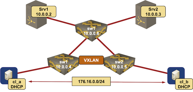
Lab topology diagram
  Interface                  IPv4 address  Description
================================================================================
srv1 (10.0.0.2/32)
  GigabitEthernet2            10.1.0.1/30  srv1 -> sw3

srv2 (10.0.0.3/32)
  GigabitEthernet2            10.1.0.5/30  srv2 -> sw3

sw1 (10.0.0.4/32)
  Ethernet1                   10.1.0.9/30  sw1 -> sw2
  Ethernet2                  10.1.0.13/30  sw1 -> sw3
  Vlan1000                  172.16.0.4/24  VLAN cv1 (1000) -> [cl_a,cl_b,sw2]

sw2 (10.0.0.5/32)
  Ethernet1                  10.1.0.10/30  sw2 -> sw1
  Ethernet2                  10.1.0.17/30  sw2 -> sw3
  Vlan1000                  172.16.0.5/24  VLAN cv1 (1000) -> [cl_a,sw1,cl_b]

sw3 (10.0.0.6/32)
  Ethernet1                   10.1.0.2/30  sw3 -> srv1
  Ethernet2                   10.1.0.6/30  sw3 -> srv2
  Ethernet3                  10.1.0.14/30  sw3 -> sw1
  Ethernet4                  10.1.0.18/30  sw3 -> sw2

cl_a (10.0.0.7/32)
  GigabitEthernet0/1        172.16.0.7/24  cl_a -> [sw1,cl_b,sw2]

cl_b (10.0.0.8/32)
  GigabitEthernet0/1        172.16.0.8/24  cl_b -> [cl_a,sw1,sw2]
You can view the complete topology file on GitHub.
Adding Redundancy to DHCP Relaying
You can add redundancy to the DHCP relaying process in several ways:
- Have multiple switches with ip helper-address interface configuration connected to the same network (already covered in VXLAN and EVPN scenarios)
- Have multiple DHCP servers, and list them all in ip helper-address configuration commands.
- Use anycast IP address across multiple DHCP servers, and as the destination for ip helper-address command.
Using anycast sounds like an awesome idea. After all, DNS and DHCP run on top of UDP, and tons of people use anycast with DNS. Unfortunately, there’s a tiny difference between DNS and DHCP. While they both use unreliable transport, DNS is a stateless service, while DHCP address acquisition is a multi-step process, and DHCP servers have to keep long-term information about their clients. Trying to implement anycast-based DHCP is thus an interesting exercise.
We’ll skip the unicorn pastures and focus on the simple scenario: multiple ip helper-address commands (one per DHCP server) on ingress interfaces. It’s always worth checking how that works, but both platforms I tested (Cisco IOS/XE and Arista EOS) relay broadcast packets to all configured servers in parallel.
Device Configurations
I made the following configuration changes to the VXLAN DHCP relaying configuration:
- Edge switches forward DHCP broadcasts to two DHCP servers.
- Each DHCP server has half of the VLAN subnet in its DHCP pool to prevent address assignment conflicts1.
vlan 1000
   name cv1
!
interface Vlan1000
   description VLAN cv1 (1000) -> [cl_a,cl_b,sw2]
   ip address 172.16.0.4/24
   ip helper-address 10.0.0.2
   ip helper-address 10.0.0.3
   ip virtual-router address 172.16.0.1/24
!
interface Vxlan1
   vxlan source-interface Loopback0
   vxlan udp-port 4789
   vxlan vlan 1000 vni 101000
   vxlan vlan 1000 flood vtep 10.0.0.5
!
ip virtual-router mac-address 02:00:ca:fe:00:ff
ip dhcp excluded-address 172.16.0.4
ip dhcp excluded-address 172.16.0.1
ip dhcp excluded-address 172.16.0.5
!
ip dhcp pool p_172.16.0.0
 network 172.16.0.0 255.255.255.0
 default-router 172.16.0.1
ip dhcp excluded-address 172.16.0.1 172.16.0.128
!
ip dhcp pool p_172.16.0.0
 network 172.16.0.0 255.255.255.0
 default-router 172.16.0.1
The final device configurations are available in netlab-examples GitHub repository.
What’s Going On Behind the Scenes?
By now, you should know how the DHCP relaying process works:
- DHCP client sends a DHCP DISCOVER local broadcast
- The switches attached to the client VLAN forwards the DHCP request to all DHCP servers configured in the ip helper-address interface configuration commands.
- The source IP address of the relayed packet, and the giaddr (gateway IP address) in the forwarded DHCP request, is the unicast VLAN IP address of the relaying switch.
- Each DHCP server receives two copies of the DHCP DISCOVER request but replies with a single DHCP OFFER packet to the first DHCP REQUEST packet it received (see VXLAN DHCP relaying for more details).
- The DHCP client receives two DHCP OFFERs with different IP addresses belonging to the VLAN subnet.
Here are the relevant bits from the DHCP client log, you can view the full client and server (srv1, srv2) debugging logs on GitHub.
00:12:17: DHCP: Scan: Message type: DHCP Offer
00:12:17: DHCP: Scan: Client ID: cisco-5254.0064.6bd1-Gi0/1
00:12:17: DHCP: Scan: Server ID Option: 10.1.0.1 = A010001
00:12:17: DHCP: Scan: Subnet Address Option: 255.255.255.0
00:12:17: DHCP: Scan: Router Option: 172.16.0.1
00:12:17:    UDP  sport: 43,  dport: 44,  length: 317
00:12:17:    DHCP op: 2, htype: 1, hlen: 6, hops: 1
00:12:17:    DHCP server identifier: 10.1.0.1
00:12:17:         xid: 91D, secs: 0, flags: 8000
00:12:17:         client: 0.0.0.0, your: 172.16.0.6
00:12:17:         srvr:   0.0.0.0, gw: 172.16.0.4
00:12:17:         options block length: 69

00:12:17: DHCP: Scan: Message type: DHCP Offer
00:12:17: DHCP: Scan: Client ID: cisco-5254.0064.6bd1-Gi0/1
00:12:17: DHCP: Scan: Server ID Option: 10.1.0.5 = A010005
00:12:17: DHCP: Scan: Subnet Address Option: 255.255.255.0
00:12:17: DHCP: Scan: Router Option: 172.16.0.1
00:12:17:    UDP  sport: 43,  dport: 44,  length: 317
00:12:17:    DHCP op: 2, htype: 1, hlen: 6, hops: 1
00:12:17:    DHCP server identifier: 10.1.0.5
00:12:17:         xid: 91D, secs: 0, flags: 8000
00:12:17:         client: 0.0.0.0, your: 172.16.0.131
00:12:17:         srvr:   0.0.0.0, gw: 172.16.0.4
00:12:17:         options block length: 69
Worth noting:
- Offers are coming from two DHCP servers (10.1.0.1 and 10.1.0.5)
- Both offers are coming through the same gateway (172.16.0.4) – the directly-connected switch usually propagates the DISCOVER packet faster than the switch receiving it over VXLAN, and the servers ignore the duplicate DISCOVER packet.
We’re not done yet. While the client knows which DHCP server to use, and what IP address it might get, it still cannot use the allocated IP address. There are a few more steps in the process:
- The DHCP client sends a DHCP REQUEST message indicating which server it wants to talk with (server identifier, set to 10.1.0.1) as a local broadcast.
- Both switches propagate that local broadcast to both DHCP servers.
- The server selected in the DHCP server identifier option responds with a DHCP ACK message confirming the client IP address.
- The other server acts confused (at least Cisco IOS XE DHCP server does), complains that the client doesn’t know what it’s doing and wants to send an ASSIGNMENT FAILURE message, but then through some convoluted reasoning comes to its senses. At least that’s how I’m reading the debugging logs.
00:12:21: DHCPD: DHCPREQUEST received from client 0063.6973.636f.2d35.3235.342e.3030.3634.2e36.6264.312d.4769.302f.31.
00:12:21: DHCPD: DHCPREQUEST received on interface GigabitEthernet2.
00:12:21: DHCPD: no subnet configured for 10.1.0.5.
00:12:21: DHCPD: FSM state change INVALID
00:12:21: DHCPD: Workspace state changed from INIT to INVALID
00:12:21: DHCPD : Client request received seeing the client for first time
00:12:21: DHCPD: client rejected 172.16.0.131, sent 172.16.0.6.
00:12:21: DHCPD: server-id specified by client (0) 10.1.0.1
...
00:12:21: DHCPD: returned 172.16.0.131 to address pool p_172.16.0.0.
...
00:12:21: DHCPD: DHCPREQUEST received from client 0063.6973.636f.2d35.3235.342e.3030.3634.2e36.6264.312d.4769.302f.31.
00:12:21: DHCPD: DHCPREQUEST received on interface GigabitEthernet2.
00:12:21: DHCPD: no subnet configured for 10.1.0.5.
00:12:21: DHCPD: FSM state change INVALID
00:12:21: DHCPD: Workspace state changed from INIT to INVALID
00:12:21: DHCPD : Client request received seeing the client for first time
00:12:21: DHCPD: excluded address: 172.16.0.6
...
00:12:21: DHCPD: Finding a relay for client 0063.6973.636f.2d35.3235.342e.3030.3634.2e36.6264.312d.4769.302f.31 through relay 172.16.0.5.
00:12:21: DHCPD : Locating relay for Subnet 172.16.0.5
00:12:21: DHCPD: Option 125 not present in the msg.
00:12:21: DHCPD: Sending notification of ASSIGNMENT FAILURE:
00:12:21:   DHCPD: htype 1 chaddr 5254.0064.6bd1
00:12:21:   DHCPD: remote id 020a00000a01000500000000
00:12:21:   DHCPD: giaddr = 172.16.0.5
00:12:21:   DHCPD: interface = GigabitEthernet2
00:12:21:   DHCPD: class id 636973636f706e70
00:12:21: DHCPD: Sending notification of ASSIGNMENT_FAILURE:
00:12:21:  DHCPD: due to: CANT FORWARD
00:12:21:   DHCPD: htype 1 chaddr 5254.0064.6bd1
00:12:21:   DHCPD: remote id 020a00000a01000500000000
00:12:21:   DHCPD: giaddr = 172.16.0.5
00:12:21:   DHCPD: interface = GigabitEthernet2
00:12:21:   DHCPD: class id 636973636f706e70
00:12:21: DHCPD: cannot find a relay
Subsequent DHCP exchanges take place as unicast UDP packets between the client and the selected DHCP server. Go through the DHCP lease renewal (client, server) and DHCP address release (client, server) logs if you want to know the details, but there’s really nothing to see there.
What the Standards Say
The second DHCP shouldn’t act confused: sending a broadcast REQUEST with specified server identifier is a regular part of the DHCP address allocation process even when the DHCP clients and servers sit in the same IP subnet. This is what RFC 2131 says in step 4 of client-server interaction:
The servers receive the DHCPREQUEST broadcast from the client. Those servers not selected by the DHCPREQUEST message use the message as notification that the client has declined that server’s offer. The server selected in the DHCPREQUEST message commits the binding for the client to persistent storage and responds with a DHCPACK message containing the configuration parameters for the requesting client.
Regardless of how it comes to its conclusions, the second DHCP server SHOULD figure out it’s not wanted and release its address allocation.
Try It Out!
Want to run this lab on your own, or try it out with different devices? No problem:
- Make sure your preferred device supports DHCP relaying and VLANs. VXLAN support is optional, but you’ll have to modify the lab configuration file if your device doesn’t support VXLAN.
- Install netlab
- Download the relevant containers or create Vagrant boxes
- Download the DHCP relaying with redundant servers example into an empty directory
- If you want to use a relaying device that’s not Arista EOS, add a configuration template to
dhcp-relaysubdirectory. - Execute netlab up
- Enjoy! 😊
Next: Inter-VRF DHCP Relaying with Redundant DHCP Servers Continue
-
Using Cisco IOS as a component of a redundant DHCP server farm is a bad idea. You REALLY SHOULD use a DHCP server that uses a back-end database and shares client- and lease information with other DHCP servers. Lacking that, I decided to go for the brute-force approach: split address pools. ↩︎