Can BGP Route Reflectors Really Generate Forwarding Loops?
TL&DR Summary: Yes (if you’re clumsy enough).
A while ago I read Impact of Graceful IGP Operations on BGP – an article that described how changes in IGP topology result in temporary (or sometimes even permanent) forwarding loops in networks using BGP route reflectors.
Is the problem real? Yes, it is. Could you generate a BGP RR topology that results in a permanent forwarding loop? Yes. It’s not that hard.
I Think I Broke It
Here’s a particularly broken topology (connections with arrows are BGP sessions, R1 and R2 are route reflectors, all other routers are their clients).
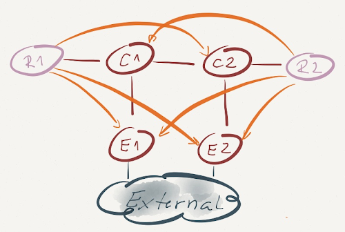
Assuming E1 and E2 advertise an identical external prefix (IP-External) over their IBGP sessions, this topology results in a permanent forwarding loop. Can you figure out why that’s the case?
Route Reflector Is Just a Router
A BGP route reflector is nothing more than a regular BGP router with a few route propagation rules bolted onto the update generation code. It still follows all the rules of BGP route processing:
- Receive routes from BGP peers;
- Install all (accepted) routes into BGP RIB;
- For every IP prefix, select the best route from all RIB routes describing that prefix;
- Advertise the best routes to BGP peers (and here’s where a route reflector deviates from standard BGP behavior – it advertises best routes to its clients regardless of how it got them).
BGP Route Selection Rules Reexamined
Route reflectors in our diagram (R1 and R2) receive BGP routes for the IP-External prefix from E1 and E2. Assuming the updates are identical, R1 and R2 select their best BGP route based on lowest IGP cost – R1 will select the route advertised by E1; R2 will select the route advertised by E2.
BGP Route Reflectors and Forwarding Topology
Next step in our forwarding loop creation: R1 advertises the best route to IP-External with E1 as the BGP next hop to all its clients (E1, E2 and C2). E1 and E2 ignore the update (they both have a better route), C2 uses it.
Similarly, R2 advertises its best route to IP-External with E2 as BGP next hop to E1, E2 and C1. C1 uses the advertised route.
Based on its BGP table (copied into IP routing table and FIB) C1 sends the traffic for IP-External toward BGP next hop E2. Recursive next hop resolution results in C2 being the true next hop. Likewise, C2 sends the traffic for IP-External to C1. Bingo! A permanent forwarding loop.
Can you prevent the forwarding loop? You can avoid most of them with a good design – make sure your BGP sessions don’t deviate too much from the forwarding topology. Ideally, all BGP route reflectors in a cluster would have equal IGP cost to all BGP next hops.
Alternatively, if you’re OK with a slightly slower convergence, you could establish IBGP sessions across physical links (so they’re guaranteed to follow the forwarding topology) and turn every single router into a BGP route reflector ... effectively turning BGP into RIP.
MPLS is the answer. What was the question?
OK, good design clearly helps. But can you prevent the forwarding loops? Sure – MPLS is always the right answer (these days it might be LISP, but I’m digressing).
If you deploy LDP-based MPLS forwarding in your BGP network, the packets toward the BGP next hops always carry an LDP-generated label for the BGP next hop (not the external prefix) and thus get across your autonomous system without a single additional L3 lookup. Even if the forwarding tables derived from BGP information don’t make much sense, the packets still get to some egress router (although they might take a suboptimal path).
Would you agree with the above statements?
It's difficult to emulate something similar in production...
Nikolay
http://www.cisco.com/en/US/docs/ios/12_4t/12_4t11/htbgpsoo.html
Thanks
Good post!
But I would be really surprised if I saw anything like this in real life. RR is there to resolve the overhead caused by IBGP full-mesh. And the reason for IBGP full-mesh is to ensure all IBGP speakers “see” the same. Back to this topology, E1,E2 are the common clients for R1 and R2, however, C1 and C2 belong to only one RR. If we remove the RR from the picture, we would see a topology that IBGP full mesh is not there. So to resolve this problem, just have C1 join the Cluster with R1 and C2 join the cluster with R2.
I hope you wouldn't see anything like this in real life -- as I wrote, you have to be clumsy enough ;)
However, were you unlucky enough to have just the right combination of BGP sessions failing... Nah, that would never happen, we all monitor the state of our BGP sessions and react the moment they flap, don't we 😜