Long-distance IRF Fabric: Works Best in PowerPoint
HP has commissioned an IRF network test that came to absolutely astonishing conclusions: vMotion runs almost twice as fast across two links bundled in a port channel than across a single link (with the other one being blocked by STP). The test report contains one other gem, this one a result of incredible creativity of HP marketing:
For disaster recovery, switches within an IRF domain can be deployed across multiple data centers. According to HP, a single IRF domain can link switches up to 70 kilometers (43.5 miles) apart.
You know my opinions about stretched cluster… and the more down-to-earth part of HP Networking (the people writing the documentation) agrees with me.
Let’s assume someone is actually brave enough to deploy a network using the design shown in the following figure with switches in two data centers merged into an IRF fabric (according to my Twitter friends this design was occasionally promoted by some HP-certified instructors):
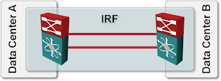
Stretched IRF fabric design
The IRF documentation for the A7500 switches (published in August 2011)1 contains the following facts about IRF partitions (split IRF fabric) and Multi-Active Detection (MAD) collisions (more commonly known as split brain problems):
The partitioned IRF fabrics operate with the same IP address and cause routing and forwarding problems on the network.
No surprise there, we always knew that split subnets cause interesting side effects, but it’s nice to see it acknowledged.
It's interesting to note, though, that pure L2 solution might actually work ... but the split subnets would eventually raise their ugly heads in adjacent L3 devices.
During an IRF merge, the switches of the IRF fabric that fails the master election must reboot to re-join the IRF fabric that wins the election.
Hold on – I lose the inter-DC link(s), reestablish them, and then half of the switches reboot. Not a good idea.
Let’s assume the above design is “extended” with another bright idea – to detect split brain scenarios, the two switches run BFD over an alternate path (could be the Internet) to detect split brain events. According to the manual:
An IRF link failure causes an IRF fabric to divide into two IRF fabrics and multi-active collision occurs. When the system detects the collision, it holds a role election between the two collided IRF fabrics. The IRF fabric whose master’s member ID is smaller prevails and operates normally. The state of the other IRF fabric transitions to the recovery state and temporarily cannot forward data packets.
Isn’t that great – not only have you lost the inter-DC link, you’ve lost one of the core switches as well.
Summary: As always, just because you can doesn’t mean you should ... and remember to be wary when consultants and marketing people peddle ideas that seem too good to be true.
What Are the Alternatives?
As I’ve explained in the Data Center Interconnects webinar (available as recording or part of the yearly subscription or Data Center Trilogy), there are at least two sensible alternatives if you really want to implement layer-2 DCI and have multiple parallel layer-1 links (otherwise IRF wouldn’t work either)
Bundle multiple links in a port channel between two switches. If you’re not concerned about device redundancy (remember: you can merge no more than two high-end switches in an IRF fabric), use port channel between the two DCI switches.
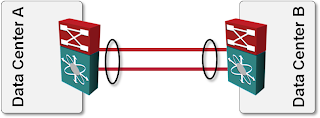
DCI link implemented with LAG bundle
Use IRF (or any other MLAG solution) within the data center and establish a port channel between two IRF (or VSS or vPC) clusters. This design results in full redundancy without unexpected reloads or other interesting side effects (apart from the facts that Earth curvature didn't go away, Earth still orbits the Sun and not vice versa, and split subnets still don’t work).
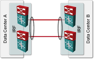
DCI link implemented as an MLAG bundle
-
HP managed to break all links to their product documentation links I had in this blog post. I have better things to do than chasing them across Internet Archive; I left the links intact in case you want to do that. ↩︎
1. Talking about only HP IRF technology and not about the HP boxes, we shouldn´t assume that there are only two switches in IRF domain, one in the main site and another on in backup site. In fact, HP has products that can operate with more than two switches in one IRF domain, such as, HP 5830, HP 5820, HP 5800, HP 10500 (future) and HP 12500 (future). Said that, anyone is crazy enough to setup a Data Center with only one DC Core, which means a SPOF (single point of failure) certainly. A DC specialist could create an IRF domain with 4 unit boxes and deploy at least two of them in each site.
2. MAD doesn´t impact the operation of switches once the link between IRF boxes goes down, because they are in the different sites and it seems to them like a shutdown in the IRF, where the secondary keeps up and running during disaster time. Let me explain that in details: when we have a IRF domain with two switches in the same subnet and the IRF links between go down, the secondary switch monitors the ARP packets from master to avoid that two switches forward the packets, causing the looping (MAD technology). However, when we shut down the master switch in IRF domain, the secondary assumes the main function and keep the forwarding of packets. In fact, when we have IRF deployed in long distance links and these links go down, the secondary switch assumes the main function, once that he didn´t monitor any ARP packet from master switch; in other words; this situation is a split of IRF domain, where the both keep up and running. If it wouldn´t work like that, why HP would use IRF?
Since we setup the information above, all premises mentioned by author in this article became invalids and affect directly the credibility of this article.
Study a little bit more and update this information, please.
Indeed I describe IRF technology (and any other technology I write about) from my point of view - that's the value my readers find in my blog. I never claimed I'm an expert in every technology I describe and vendors have contacted me numerous times to help me get the facts straight. You (or anyone else from HP) has the same option, just use the "contact me" link in the header of each page.
Next, let's talk about credibility. Everyone who clicks the "About" link on my blog can learn who I am, what I'm doing and what my standpoints are. You decided not to disclose who you are and what your affiliation with HP is. Still, I have no problem with that, but it might affect your credibility in some readers' eyes.
I usually judge how credible something is based on purely technical facts, so let's walk through them.
(A) Two or four switches in an IRF domain. You just confirmed what I wrote - today, you can link only two high-end switches in an IRF domain. Using stackable switches to build your data center? Sure, go ahead ... but that does tell a lot about the type of data centers you build.
(B) Your description of what happens after the link failure is correct (and does not contradict anything I wrote in the article). You will, however, get split subnet issues regardless of how many devices you have in the IRF fabric - that's a simple fact of life for any L2 DCI and cannot be talked away.
(C) You might want to check HP documentation (I read the documentation for A7500 and A5800) to see what happens after the DCI link is reestablished. According to the HP documentation, one of the A7500's will reload and one part of the A5800 partitioned cluster will go into "failure recovery" mode and effectively block itself.
Yet again, I am not criticizing the IRF technology (which is approximately as good as any other similar technology), but the particular design (inter-DC IRF) which simply doesn't make sense, more so as there's a completely safe alternate design I presented in the article.
Now, I can't help if someone designed and deployed inter-DC IRF and now has a credibility problem because of my article. The facts are as they are, at least according to publicly available documentation from HP. If you still feel I've misinterpreted the facts, let me know.
Ivan
Marketing departments get a little overzealous because the technology is really, really good. Unfortunately they sometimes miss basic good design principals. On the bright side F5 fixes all of the potential sun, moon, split subnet issues with the introduction of unicorn tears into BIG LTM 10. Great stuff really!
I personally feel that this kind of healthy critical reasoning is great and I appreciate the fact that it's applied liberally to all of the vendors. although you have been a little snarky on HP lately ;)
Please stop. It hurts my feelings. :)
@netmanchris
Thanks for the reply. I agree IRF is a good technology and has evolved significantly during the last 18 months (if I remember correctly, partitions were deadly a year ago).
BTW, why would a two-fabric solution with MLAG be different from budgetary perspective than the inter-DC-fabric one? Licensing?
As for snarkiness - I try to apply it fairly across all vendors :-P Just read some IPv6-in-DC posts 8-)
All the best!
Ivan
From an HP perspective, there's no difference in the licensing. It's more the seperation of the shared-fate domain.
As you know, technologies like IRF only become a good idea if the downstream devices are dual homed to the virtualized switch ( Is there an industry standard term to describe a switch in a VSS/IRF/Virtual Chassis configuration?). Unless you are dual-homed, there's no point ( in my opinion) in stretching your control-plane across the data centers.
Where I have seen this applied in a VERY cool design is by doing multi-floor closets in enterprise lan which do have the appropriate calbing infrastructure in place to allow for this from a stackable switch.
This allows us to have the redundency and fast failover, the redundant paths and the single point of managment which is not available today in any Cisco stackable switches. Very cool in an enterprise LAN design scenario.
My favorite Ivan was the thoughts on VMWare's motivations in the packet pushers podcast. :)
cheers!
@netmanchris
If you suppose that the option number two is the central DC - part of the 3 tiers DC disaster recovery design ( this is: this is the central/operation DC which connects to the local backup DC center and to the remote backup DC = disaster recovery approch), then if you have branches offices, you could balance their access to the DC by connecting one branch to to each DC: operation DC, local backup DC and remote backup DC. This way the 3 DCs have to be down for the brabch to loose connectivity to the DC.
Geo IRF can come into the play here between the Branch offices. Lets suppose that apart from the branch offices requirement to access the DC they also each have their own applications and requirement that must be localy served. Then geo IRF comes into the play by enabling between the branches a level of disaster recovery for these requirements too up to LH70 distance.
Nota Bene: I used to work for 3Com and do not work anymore for HP.
Last but not least, I like much reading from your blog. Though sometime I get the impression that you know well and good only when it is about Cisco technology.
Anyway! Thanks for you good writtings!
A+
Thanks for the feedback!
Ivan
I'm in the process of evaluating equipment to replace our aging switches on a ring involving 5 sites.
I'd like to know your thoughts about using IRF to eliminate STP on this ring. There would be only one logical link between any two buildings. So in my reasoning, aside from losing two links/switches at the same time, I should not encounter any problems with split-brain or whatever, right?
The only real problem would be updating the switches' software as an IRF domain needs to update all switches at the same time.
Thanks
Hi Ivan,
I had a thought about this kind of setup last year.
I was not happy with the setup, but basically I had 2 options:
-1. - 2 VC of 2 members, each VC in 1 DC, connected via 2*10Gbps in a LAG (same as your "Use IRF within the data center" proposed solution) -2. - 1 VC of 4 members, accross 2 DC, connected via 2*10Gbps as the VC link
One of these switch had to do the inter VLAN routing.
I was concerned that the trafic coming from DC-B and going to DC-B will have to go to DC-A to be routed. For the 1st option, I knew there was nothing to do. For the 2nd one, I had a hope.
I reached the vendor (Alcatel-Lucent Enterprise, and switches are 4*OS6900-X40) and he told me that, in their VC implementation, only the first frame of a flow is sent to the VC master. The VC master then inject forwarding rules in the VC slaves and next frames are forwarded locally (in DC-B only) and so the VC link is less charged.
So I went for the option #2.
Unfortunatelly I still don't see many options when customer network is mainly Layer2.
Maybe you can have give-and-take scenario with sysadmins? Setup 2VC with 2 members, use each VC for routing. Add 2 VIP, each living as active in different DC, and agree with sysadmins that by default hosts located in dc1 should use gw1, hosts in dc2 use gw2. It should be rule for sysadmin, if they setup properly def gw on os, routing will be optimal. I know that is not clean solution from networkig perspective, and will bring nrw problems, but....
@Piotr: I had a customer doing exactly that. Trying to figure out all possible redundancy scenarios with various WAN links, Internet connections, and edge nodes failing (with traffic going through firewalls based on static routes) was a nightmare.
It's much better (and simpler in the long run) to do a proper design without stretched VLANs, like what Adrian described in recent blog posts:
https://blog.ipspace.net/2021/02/simple-dr-design.html