… updated on Monday, December 28, 2020 18:03 UTC
PE-to-PE Troubleshooting in MPLS VPN Networks
End-to-end troubleshooting of MPLS VPN solutions is one of the more complex network troubleshooting tasks. On top of several sophisticated technologies and protocols used in MPLS VPN solutions, we have to deal with customer-to-provider interaction on the IP routing protocol level, which makes the troubleshooting efforts even more convoluted.
To minimize the impact of your customers on your troubleshooting efforts, you might want to start with the PE-to-PE troubleshooting. When used as the first step in your troubleshooting process, the PE-PE tests will bypass customer errors, intra-site customer routing problems, PE-CE interactions, and route redistribution issues.
The easiest way to perform PE-to-PE connectivity tests is to create a dummy VRF on the PE routers under consideration and test the connectivity between loopback interfaces assigned to the newly created VRF:
- Allocate a route distinguisher (RD) and route target (RT) that is not used anywhere else in the MPLS VPN domain.
- Create a VRF on one of the PE routers using the test RD and RT. Wait for the multiprotocol BGP (MP-BGP) network to converge.
- Inspect the BGP table associated with the selected RD (show ip bgp vpnv4 rd RD). The table should be empty indicating that no other VPN uses the same RD.
- Inspect the BGP table of the new VRF (show ip bgp vpnv4 vrf name). The table should be empty indicating that no other VPNv4 routes have the same RT.
- Create a loopback interface, assign it to the new VRF and give it an IP address.
- Create the BGP address family associated with the new VRF and redistribute connected routes into BGP. Two-way redistribution is not required as you’re not using a PE-CE routing protocol.
- Repeat steps 2, 5 and 6 on all other PE routers you want to test.
After the loopback IP addresses have been redistributed into MP-BGP and propagated throughout the network, you’re ready to start troubleshooting.
Perform these steps to verify PE-to-PE connectivity for the new VRF:
- Inspect the BGP table associated with the new VRF on all PE routers under test and verify that they contain all loopback addresses you’ve configured. Missing prefixes indicate BGP-related route propagation problems.
- Perform traceroute within the VRF with the traceroute vrf name destination source source command. The traceroute vrf command will either display hop-by-hop path through the network or fail at the first hop regardless of the actual location of the problem.
- If the traceroute command fails, use the BGP table in the new VRF to find the next-hop addresses of the remote PE-routers. Perform MPLS traceroute toward the next-hop addresses to identify the actual location of the broken end-to-end LSP.
Sample troubleshooting session
Sample MPLS VPN troubleshooting illustrated in this section is performed between the routers PE-A and PE-C in the following network.
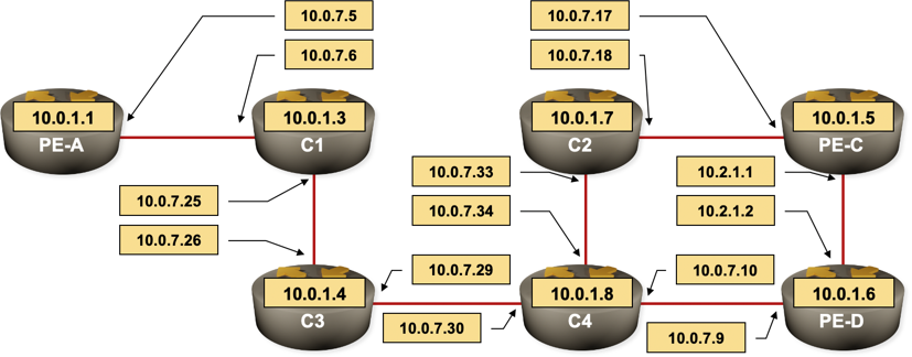
Sample MPLS VPN network
New RD (65000:101) and RT (65000:101) were allocated for test purposes. VRF Test is created on the PE-A:
ip vrf Test
 rd 65000:101
 route-target export 65000:101
 route-target import 65000:101
The new route targets configured on PE-A affect the automatic MP-BGP inbound filters. You should wait a few seconds before checking the BGP table for routes having test RD or RT. After you’ve confirmed that no existing routes in the MPLS VPN network use the test RD/RT, continue with the configuration. The final configuration of VRF Test on PE-A and PE-C is shown in the following listings:
PE-A#show running-config vrf Test
Building configuration...

Current configuration : 304 bytes
ip vrf Test
 rd 65000:101
 route-target export 65000:101
 route-target import 65000:101
!
router bgp 65000
 !
 address-family ipv4 vrf Test
  no synchronization
  redistribute connected
 exit-address-family
!
interface Loopback101
 ip vrf forwarding Test
 ip address 192.168.0.1 255.255.255.255
end
PE-C#show running vrf Test
Building configuration...

Current configuration : 304 bytes
ip vrf Test
 rd 65000:101
 route-target export 65000:101
 route-target import 65000:101
!
router bgp 65000
 !
 address-family ipv4 vrf Test
  no synchronization
  redistribute connected
 exit-address-family
!
interface Loopback101
 ip vrf forwarding Test
 ip address 192.168.0.2 255.255.255.255
end
When the BGP convergence completes, inspect the VPNv4 BGP entries associated with VRF Test on PE-A and PE-C. Both tables should contain two host routes:
PE-A#show ip bgp vpnv4 vrf Test
BGP table version is 5, local router ID is 10.0.1.1
Status codes: s suppressed, d damped, h history, * valid, > best, i - internal,
              r RIB-failure, S Stale
Origin codes: i - IGP, e - EGP, ? - incomplete

   Network          Next Hop            Metric LocPrf Weight Path
Route Distinguisher: 65000:101 (default for vrf Test)
*> 192.168.0.1/32   0.0.0.0                  0         32768 ?
*>i192.168.0.2/32   10.0.1.5                 0    100      0 ?
Perform the traceroute vrf command on PE-A. In the sample network, the initial test has failed:
PE-A#traceroute vrf Test 192.168.0.2 source 192.168.0.1

Type escape sequence to abort.
Tracing the route to 192.168.0.2

  1  *  *  *
The traceroute mpls command should reveal the source of the problem: in our scenario, it was an unlabeled interface between C4 and C3:
PE-A#traceroute mpls ipv4 10.0.1.5/32
Tracing MPLS Label Switched Path to 10.0.1.5/32, timeout is 2 seconds

Codes: '!' - success, 'Q' - request not sent, '.' - timeout,
  'L' - labeled output interface, 'B' - unlabeled output interface,
  'D' - DS Map mismatch, 'F' - no FEC mapping, 'f' - FEC mismatch,
  'M' - malformed request, 'm' - unsupported tlvs, 'N' - no label entry,
  'P' - no rx intf label prot, 'p' - premature termination of LSP,
  'R' - transit router, 'I' - unknown upstream index,
  'X' - unknown return code, 'x' - return code 0

Type escape sequence to abort.
  0 10.0.7.5 MRU 1500 [Labels: 23 Exp: 0]
I 1 10.0.7.6 MRU 1500 [Labels: 24 Exp: 0] 12 ms
B 2 10.0.7.26 MRU 1504 [No Label] 76 ms
B 3 10.0.7.26 MRU 1504 [No Label] 64 ms
B 4 10.0.7.26 MRU 1504 [No Label] 76 ms
After the mpls ip command was entered on the correct interface on C3, the end-to-end LSP was established and both traceroute mpls and traceroute vrf were able to reach PE-C from PE-A:
PE-A#traceroute mpls ipv4 10.0.1.5/32
Tracing MPLS Label Switched Path to 10.0.1.5/32, timeout is 2 seconds

Codes: '!' - success, 'Q' - request not sent, '.' - timeout,
  'L' - labeled output interface, 'B' - unlabeled output interface,
  'D' - DS Map mismatch, 'F' - no FEC mapping, 'f' - FEC mismatch,
  'M' - malformed request, 'm' - unsupported tlvs, 'N' - no label entry,
  'P' - no rx intf label prot, 'p' - premature termination of LSP,
  'R' - transit router, 'I' - unknown upstream index,
  'X' - unknown return code, 'x' - return code 0

Type escape sequence to abort.
  0 10.0.7.5 MRU 1500 [Labels: 23 Exp: 0]
I 1 10.0.7.6 MRU 1500 [Labels: 24 Exp: 0] 4 ms
I 2 10.0.7.26 MRU 1500 [Labels: 20 Exp: 0] 8 ms
I 3 10.0.7.30 MRU 1500 [Labels: 17 Exp: 0] 16 ms
I 4 10.0.7.9 MRU 1504 [Labels: implicit-null Exp: 0] 16 ms
! 5 10.2.1.1 56 ms
PE-A#traceroute vrf Test 192.168.0.2 source 192.168.0.1

Type escape sequence to abort.
Tracing the route to 192.168.0.2

  1 10.0.7.6 [MPLS: Labels 23/30 Exp 0] 8 msec 52 msec 12 msec
  2 10.0.7.26 [MPLS: Labels 24/30 Exp 0] 80 msec 12 msec 8 msec
  3 10.0.7.30 [MPLS: Labels 20/30 Exp 0] 48 msec 12 msec 20 msec
  4 10.0.7.9 [MPLS: Labels 17/30 Exp 0] 44 msec 12 msec 44 msec
  5 192.168.0.2 12 msec *  56 msec
To complete the tests, you should perform the traceroute vrf test in the opposite direction (from PE-C toward PE-A).
PE-C#traceroute vrf Test 192.168.0.1 source 192.168.0.2

Type escape sequence to abort.
Tracing the route to 192.168.0.1

  1 10.2.1.2 [MPLS: Labels 23/30 Exp 0] 56 msec 88 msec 80 msec
  2 10.0.7.10 [MPLS: Labels 24/30 Exp 0] 8 msec 12 msec 48 msec
  3 10.0.7.29 [MPLS: Labels 19/30 Exp 0] 72 msec 16 msec 12 msec
  4 10.0.7.25 [MPLS: Labels 18/30 Exp 0] 40 msec 8 msec 20 msec
  5 192.168.0.1 4 msec *  12 msec