Routed Interfaces on Layer-3 Switches and Internal VLANs
In the Router Interfaces and Switch Ports blog post, I described why we have switch ports and routed interfaces on layer-3 switches. Another blog post in the same series described the conceptual architecture of a layer-3 switch:
- All interfaces are connected to a VLAN-aware switch
- The switch interfaces could be access or trunk interfaces1.
- Each VLAN in a VLAN-aware switch can be connected to an internal router through a VLAN interface.
However, that’s not how we configure layer-3 switches. There’s a significant gap between the conceptual configuration model and the internal architecture:
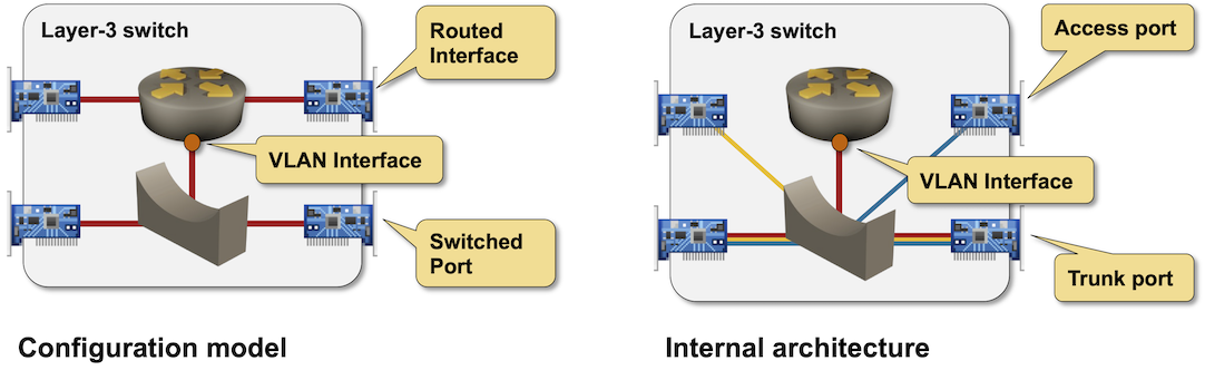
Configuration model and internal architecture of a layer-3 switch
This is how a layer-3 switch creates a routed interface:
- It takes a VLAN and declares it off-limits (an internal VLAN).
- It configures the physical (routed) interface as a VLAN access interface.
- It applies the configuration of the routed interface to the VLAN interface of the internal VLAN.
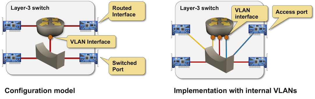
Routed interfaces on a layer-3 switch implemented with (yellow and blue) internal VLANs
Most modern switching ASICs are limited to 4096 VLANs2, meaning the internal VLANs overlap with the VLANs you configure. Fortunately, most switches display the internal VLAN allocation with a command similar to show vlan internal, allowing you to configure the VLAN range reserved for the internal VLANs.
Finally, how does a layer-3 switch implement subinterfaces on a routed interface? As expected:
- An internal VLAN is allocated for each routed subinterface.
- The VLAN tag specified for the routed subinterface is remapped into the internal VLAN tag.
Most switches support bidirectional remapping of port-level VLANs into inside VLANs, which are then used in the L2 lookups. This functionality is similar to the native VLAN implementation but uses VLAN-to-VLAN mapping instead of no-tag-to-VLAN transformation.
The VLAN remapping functionality must be used to implement routed subinterfaces (you could use the same VLAN tag on different routed subinterfaces). It can also be exposed on the switched ports and configured as VLAN translation or VLAN mapping.
- The configuration of the routed subinterface is applied to the VLAN interface of its internal VLAN.
For example, I configured two routed interfaces and two VLAN subinterfaces on an Arista EOS switch:
interface Ethernet1
   no switchport
   ip address 172.16.2.1/24
!
interface Ethernet2
   no switchport
!
interface Ethernet2.1
   encapsulation dot1q vlan 1001
   ip address 10.1.0.1/30
!
interface Ethernet2.2
   encapsulation dot1q vlan 1000
   ip address 10.1.0.5/30
The switch allocated four internal VLANs to deal with that configuration:
r1#show vlan internal usage
1006  Ethernet2.1
1007  Ethernet2.2
1008  Ethernet2
1009  Ethernet1
It’s worth noting that:
- A VLAN is allocated to the Ethernet2 interface even though the interface has no IP addresses.
- The VLAN allocated to the Ethernet2.1 and Ethernet2.2 interfaces does not match the encapsulation (VLAN tag) configured on the VLAN subinterfaces.