Layer-3-Only EVPN: Behind the Scenes
In the previous blog post, I described how to build a lab to explore the layer-3-only EVPN design and asked you to do that and figure out what’s going on behind the scenes. If you didn’t find time for that, let’s do it together in this blog post. To keep it reasonably short, we’ll focus on the EVPN control plane and leave the exploration of the data-plane data structures for another blog post.
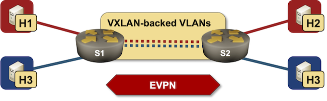
The most important thing to understand when analyzing a layer-3-only EVPN/VXLAN network is that the data plane looks like a VRF-lite design: each VRF uses a hidden VLAN (implemented with VXLAN) as the transport VLAN between the PE devices.
Don’t believe me? Let’s start the lab (using Arista cEOS containers) and check whether that’s true ;)
Device Configuration
Before starting our journey, let’s review the relevant parts of the Arista cEOS device configuration (taken from S1):
vrf instance bluerd 65000:2!vrf instance redrd 65000:1!interface Ethernet1description s1 -> s2mtu 1600mac-address 52:dc:ca:fe:01:01no switchportip address 10.1.0.1/30ip ospf network point-to-pointip ospf area 0.0.0.0!interface Ethernet2description s1 -> h1 [stub]mac-address 52:dc:ca:fe:01:02no switchportvrf redip address 172.16.0.1/24!interface Ethernet3description s1 -> h3 [stub]mac-address 52:dc:ca:fe:01:03no switchportvrf blueip address 172.16.2.1/24!interface Loopback0ip address 10.0.0.1/32ip ospf area 0.0.0.0!interface Vxlan1vxlan source-interface Loopback0vxlan udp-port 4789vxlan vrf blue vni 200001vxlan vrf red vni 200000!ip routingip routing vrf blueip routing vrf red!router bgp 65000router-id 10.0.0.1no bgp default ipv4-unicastbgp advertise-inactiveneighbor 10.0.0.2 remote-as 65000neighbor 10.0.0.2 update-source Loopback0neighbor 10.0.0.2 description s2neighbor 10.0.0.2 send-community standard extended large!address-family evpnneighbor 10.0.0.2 activate!!vrf bluerd 65000:2route-target import evpn 65000:2route-target export evpn 65000:2redistribute connected!vrf redrd 65000:1route-target import evpn 65000:1route-target export evpn 65000:1redistribute connected
- Lines 1-5: We have two VRFs (red and blue)
- Lines 7-14: The link between the switches is a P2P link with a larger MTU. We’re running P2P OSPF to speed up the convergence.
- Lines 16-28: The host-to-switch links are layer-3 links in VRFs red and blue
- Lines 37-38: We need transit VNI for the blue and red VRF
- Lines 44-51: We have an IBGP neighbor
- Lines 53-54: We’re exchanging EVPN routes with that IBGP neighbor
- Lines 57-67: Defining RD/RT values for the two VRFs. We’re also redistributing connected subnets into BGP.
Let’s Start Exploring
Using the show vlan command, it’s trivial to confirm that the switches use two VLANs (one per EVPN transit VNI) on the VXLAN interface:
s1>show vlan
VLAN  Name                             Status    Ports
----- -------------------------------- --------- -------------------------------
1     default                          active    Mt1
4093* VLAN4093                         active    Cpu, Vx1
4094* VLAN4094                         active    Cpu, Vx1

* indicates a Dynamic VLAN
Want to check that these are VXLAN-backed VLANs? Sure (notice how the VNI values match the values we defined in the vxlan vrf vni command):
s1>show vxlan vni
VNI to VLAN Mapping for Vxlan1
VNI       VLAN       Source       Interface       802.1Q Tag
--------- ---------- ------------ --------------- ----------

VNI to dynamic VLAN Mapping for Vxlan1
VNI          VLAN       VRF        Source
------------ ---------- ---------- ------------
200000       4094       red        evpn
200001       4093       blue       evpn
Now we know what the data-plane topology looks like. Next, let’s focus on the forwarding tables:
s1>show ip route vrf red bgp
...

 B I      172.16.1.0/24 [200/0]
           via VTEP 10.0.0.2 VNI 200000 router-mac 00:1c:73:eb:d5:13 local-interface Vxlan1
As expected, the BGP (EVPN) route for 172.16.1.0/24 uses the VXLAN interface and the next-hop MAC address 00:1c:73:eb:d5:13. There is no next-hop IP address (apart from remote VTEP), as the switches don’t assign IP addresses to the transit VLAN.
Where does S1 get the remote MAC address? Glad you asked ;) Let’s explore the EVPN routes for the red VRF:
s1#show bgp evpn rd 65000:1 detail
BGP routing table information for VRF default
Router identifier 10.0.0.1, local AS number 65000
BGP routing table entry for ip-prefix 172.16.0.0/24, Route Distinguisher: 65000:1
 Paths: 1 available
  Local
    - from - (0.0.0.0)
      Origin IGP, metric -, localpref -, weight 0, tag 0, valid, local, best, redistributed (Connected)
      Extended Community: Route-Target-AS:65000:1 TunnelEncap:tunnelTypeVxlan EvpnRouterMac:00:1c:73:ff:68:31
      VNI: 200000
BGP routing table entry for ip-prefix 172.16.1.0/24, Route Distinguisher: 65000:1
 Paths: 1 available
  Local
    10.0.0.2 from 10.0.0.2 (10.0.0.2)
      Origin IGP, metric -, localpref 100, weight 0, tag 0, valid, internal, best
      Extended Community: Route-Target-AS:65000:1 TunnelEncap:tunnelTypeVxlan EvpnRouterMac:00:1c:73:eb:d5:13
      VNI: 200000
The EVPN transit tunnel encapsulation (VXLAN), VNI, and remote MAC address are encoded as extended BGP communities in every EVPN RT5 (IP prefix) update.
But why do we need the EVPN router MAC addresses on the transit VXLAN segment? Wouldn’t the VNI and remote VTEP be good enough? Unfortunately, VXLAN is nothing more than a transport mechanism that carries Ethernet frames over UDP, and every Ethernet frame must have a source- and a destination MAC address.
Want to see those MAC addresses in the forwarding tables? Let’s explore the VXLAN- and VLAN MAC address tables:
s1#show vxlan address-table
          Vxlan Mac Address Table
----------------------------------------------------------------------

VLAN  Mac Address     Type      Prt  VTEP             Moves   Last Move
----  -----------     ----      ---  ----             -----   ---------
4093  001c.73eb.d513  EVPN      Vx1  10.0.0.2         1       2:16:21 ago
4094  001c.73eb.d513  EVPN      Vx1  10.0.0.2         1       2:16:21 ago
s1#show mac address-table
          Mac Address Table
------------------------------------------------------------------

Vlan    Mac Address       Type        Ports      Moves   Last Move
----    -----------       ----        -----      -----   ---------
4093    001c.73eb.d513    DYNAMIC     Vx1        1       2:19:02 ago
4094    001c.73eb.d513    DYNAMIC     Vx1        1       2:19:01 ago
But where do the local MAC addresses come from? As you know, every VLAN (including the internal VLANs) has an associated VLAN interface on a layer-3 switch:
s1#show interfaces vlan4093
Vlan4093 is up, line protocol is up (connected)
  Hardware is Vlan, address is 001c.73ff.6831 (bia 001c.73ff.6831)
  No Internet protocol address assigned
  IPv6 link-local address is fe80::21c:73ff:feff:6831/64
  No IPv6 global unicast address is assigned
  IP MTU 9164 bytes (default)
  Up 2 hours, 20 minutes, 10 seconds
s1#show interfaces vlan4094
Vlan4094 is up, line protocol is up (connected)
  Hardware is Vlan, address is 001c.73ff.6831 (bia 001c.73ff.6831)
  No Internet protocol address assigned
  IPv6 link-local address is fe80::21c:73ff:feff:6831/64
  No IPv6 global unicast address is assigned
  IP MTU 9164 bytes (default)
  Up 2 hours, 20 minutes, 13 seconds
To recap:
- A layer-3 switch creates a VLAN for every VXLAN segment.
- A local (switch) MAC address is assigned to every VLAN segment (VLAN interface)1. The same MAC address is usually used for all VLAN segments.
- The local MAC address and the transit VNI attached as extended BGP communities to every VRF IP prefix (RT5) EVPN route
- The remote MAC address and the associated transit VNI are used to build the forwarding entry on the ingress routers.
Next: Using Multiple Transit VNIs per EVPN VRF Continue
-
And I have no idea what they use to make the lower 24 bits unique, particularly in a virtual environment where all the containers are cloned from the same image. ↩︎
how does this actually scale in larger environments or even existing environments where majority of the VLANs have already been consumed?
ps. don't deploy vxlan, however i'd like to understand more
The only VLANs needed in this setup are the internal VLANs used for VXLAN-based transport (one per VRF). They are assigned dynamically (as needed) and don't have to match across the PE devices.
However, if you deployed all 409x VLANs on every access switch, you have a bigger problem ;)
Regarding "the transit VNI does not have to match across the PE devices" you are going to cover it in the future post, I speculate there could be a chipset limitations forcing the VNI to be the same or "symmetric". This limitation is documented for Juniper's ACX7100, so is this the case for anything Jericho2 based?
The obvious answer is "We don't know" (thank you, Broadcom, we love your NDAs), but I suspect it might be more of a case of a vendor doing a less-than-optimal job (in the case of L3VPN, L2VPN is another story)
AFAIK, not all the vendors require to have dynamic virtual VLANs to map a L3VNI.
I.e., Aruba CX and Dell OS10 don't (and - despite I hope nobody's doing that - you can potentially use for your network all the VLAN IDs).
Additionally, they also allow to statically set the router-mac to use on the L3VNI and RT5 announces (i.e. https://www.arubanetworks.com/techdocs/AOS-CX/10.08/HTML/vxlan/Content/Chp_EVPN/EVPN_cmds/vir-mac.htm)
Also Linux (frr, vyos, ...) does not require dynamic vlans, but instead requires to allocate a dedicated bridge interface (with no bridge slaves, apart from the vxlan device which maps the vni id) to be used for r-macs.
> AFAIK, not all the vendors require to have dynamic virtual VLANs to map a L3VNI.
Don't require or don't show them? Also, what they're doing in a VM might be different from what they're doing in ASIC.
> Also Linux (frr, vyos, ...) does not require dynamic vlans, but instead requires to allocate a dedicated bridge interface
Correct, but how does that map into ASIC setup on Cumulus Linux (or any other switch using FRRouting)?
>> AFAIK, not all the vendors require to have dynamic virtual VLANs to map a L3VNI.
> Don't require or don't show them? Also, what they're doing in a VM might be different from what they're doing in ASIC.
Talking about (BCM) ASIC here.
Let's put this way: they do not require a strict VLAN, allowing the user to use all the possible VLANs ID (I know this because I did a qualification testing using all the vlans at the same time plus vxlan distributed irb).
But since you triggered my curiosity, I went into the BCM shell to check.
Seems that BCM chipsets allows to define a VLAN ID > 4096, and so vendor uses them for vxlan operations. This is what I see from the BCM shell on a fabric leaf which has only l3 vnis:
And
00:00:66:66:05:06is the rMAC I statically defined on this leaf.So, a virtual interface, with VLAN id 28XXX is created for each VRF/L3 VNI, with the defined mac.
But no VLAN space of the ASIC is used:
Then the virtual interface is used as egress operation for the VRF's routes. i.e.,
in the above case, a specific route is sent to the rmac 00:00:66:66:01:06, which is another leaf, using the virtual interface 16381.
WRT Cumulus, if I'm not wrong it uses the Linux switchdev framework. Unfortunately it seems the documentation is not complete, so if a kernel programmer could have a look into it we can answer also that point ;)
Wow. Thanks a million for that deep dive!
As for Cumulus, it probably uses the Linux switchdev framework now that it only works on the Mellanox hardware 🤷♂️ (it used a proprietary translator between netlink and Broadcom SDK in the past)
Hi Ivan,
Minh Ha asked a question in a previous post I've linked at the bottom and I just happened to stumble into the same question. It comes from Hannes Gredler's "The Complete IS-IS Routing Protocol." The question specifically regards the potential loop that could be created if you actually ran a routing protocol over the tunnel interface. The author starts by saying,
"Things behave really badly if the total IGP cost over the tunnel undermines the total topologies’ cost. What happens next is that the tunnel “wraps” around itself, ultimately causing a meltdown of the entire network."
He finishes the paragraph with this: "Because no Hellos are sent down the tunnel there is no infinite recursion problem."
I can't see why you couldn't run an IGP over the tunnel. But, of course, this creates redundant state, and with it more churn, so you shouldn't run a real IIH-based adjacency. The tunnel itself is based on other next-hops, so forwarding adjacency forgoes a real adjacency IIH-based adjacency because we can tie tunnel state to whether or not we have an IGP route to the endpoint.
I've been sitting with pen and paper to try and make heads or tails of what he's saying here and I can't seem to wrap my brain around what he means.
Any insight would be greatly appreciated!!!
https://blog.ipspace.net/2020/08/worth-reading-default-isis-configuration-prefix-bloat/