netlab: VRF Lite over VXLAN Transport
One of the comments I received after publishing the Use VRFs for VXLAN-Enabled VLANs claimed that:
I’m firmly of the belief that VXLAN should be solely an access layer/edge technology and if you are running your routing protocols within the tunnel, you’ve already lost the plot.
That’s a pretty good guideline for typical data center fabric deployments, but VXLAN is just a tool that allows you to build multi-access Ethernet networks on top of IP infrastructure. You can use it to emulate E-LAN service or to build networks similar to what you can get with DMVPN (without any built-in security). Today we’ll use it to build a VRF Lite topology with two tenants (red and blue).
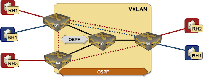
Lab topology
In our lab topology, we’ll define two VRFs, two transport VLANs, and enable VXLAN transport for those VLANs (more details in Creating VRF Lite Labs With netlab, VRF Lite Topology with VLAN Trunks and VXLAN Bridging Example):
vrfs:
  red:
  blue:

vlans:
  red_transport:
    vrf: red
  blue_transport:
    vrf: blue

vxlan.vlans: [ red_transport, blue_transport ]
Next, we’ll define groups of devices:
- Linux hosts need no extra configuration modules
- pe devices will run OSPF with the core devices and within the VRFs. They will also need VXLAN transport.
- core devices run OSPF.
groups:
  hosts:
    members: [ rh1, rh2, rh3, bh1, bh2 ]
    module: []
    device: linux
  pe:
    module: [ vxlan,ospf ]
    members: [ s1,s2,s3 ]
  core:
    members: [ c ]
    module: [ ospf ]
Now for a trick: we’ll define a group of PE-devices that provides services to the red tenant and another group of PE-devices that provides services to the blue tenant1 (more details in VXLAN Router-on-a-Stick):
groups:
  red_team:
    module: [ vlan,vrf ]
    members: [ s1, s2, s3 ]
    vlans:
      red_transport:
  blue_team:
    module: [ vlan,vrf ]
    members: [ s1, s2 ]
    vlans:
      blue_transport:
Finally, we have to define nodes and links (you can also view the final lab topology on GitHub).
nodes: [ rh1, rh2, rh3, bh1, bh2, s1, s2, s3, c ]

links:
- s1-c
- s2-c
- s3-c

# Red VRF
- rh1:
  s1:
  vrf: red
- rh2:
  s2:
  vrf: red
- rh3:
  s3:
  vrf: red

# Blue VRF
- bh1:
  s1:
  vrf: blue
- bh2:
  s2:
  vrf: blue
Now we’re ready to roll. Execute netlab up2, wait for OSPF sessions to be established, and explore the OSPF neighbors and routing tables on S1:
s1#sh ip ospf neighbor
Neighbor ID     Instance VRF      Pri State                  Dead Time   Address         Interface
10.0.0.9        1        default  0   FULL                   00:00:31    10.1.0.1        Ethernet1
10.0.0.7        101      blue     0   FULL                   00:00:33    172.16.1.7      Vlan1001
10.0.0.8        100      red      1   FULL/DR                00:00:31    172.16.0.8      Vlan1000
10.0.0.7        100      red      1   FULL/BDR               00:00:31    172.16.0.7      Vlan1000
s1#sh ip route vrf red

VRF: red
...
Gateway of last resort is not set

 C        172.16.0.0/24 is directly connected, Vlan1000
 C        172.16.2.0/24 is directly connected, Ethernet2
 O        172.16.3.0/24 [110/20] via 172.16.0.7, Vlan1000
 O        172.16.4.0/24 [110/20] via 172.16.0.8, Vlan1000
s1#sh ip route vrf blue

VRF: blue
...
Gateway of last resort is not set

 C        172.16.1.0/24 is directly connected, Vlan1001
 C        172.16.5.0/24 is directly connected, Ethernet3
 O        172.16.6.0/24 [110/20] via 172.16.1.7, Vlan1001
For the two readers who haven’t installed netlab yet: here’s the Arista cEOS configuration for S1:
vlan 1000
   name red_transport
!
vlan 1001
   name blue_transport
!
vrf instance blue
   rd 65000:2
!
vrf instance red
   rd 65000:1
!
interface Ethernet1
   description s1 -> c
   no switchport
   ip address 10.1.0.2/30
   ip ospf network point-to-point
   ip ospf area 0.0.0.0
!
interface Ethernet2
   description s1 -> rh1 [stub]
   no switchport
   vrf red
   ip address 172.16.2.6/24
   ip ospf network point-to-point
   ip ospf area 0.0.0.0
!
interface Ethernet3
   description s1 -> bh1 [stub]
   no switchport
   vrf blue
   ip address 172.16.5.6/24
   ip ospf network point-to-point
   ip ospf area 0.0.0.0
!
interface Loopback0
   ip address 10.0.0.6/32
   ip ospf area 0.0.0.0
!
interface Management0
   ip address 192.168.121.106/24
   no lldp transmit
   no lldp receive
!
interface Vlan1000
   description VLAN red_transport (1000) -> [s2,s3]
   vrf red
   ip address 172.16.0.6/24
   ip ospf area 0.0.0.0
!
interface Vlan1001
   description VLAN blue_transport (1001) -> [s2]
   vrf blue
   ip address 172.16.1.6/24
   ip ospf network point-to-point
   ip ospf area 0.0.0.0
!
interface Vxlan1
   vxlan source-interface Loopback0
   vxlan udp-port 4789
   vxlan vlan 1000 vni 101000
   vxlan vlan 1001 vni 101001
   vxlan vlan 1000 flood vtep 10.0.0.7 10.0.0.8
   vxlan vlan 1001 flood vtep 10.0.0.7
!
ip routing
ip routing vrf blue
ip routing vrf red
!
router ospf 1
   router-id 10.0.0.6
   max-lsa 12000
!
router ospf 100 vrf red
   router-id 10.0.0.6
   interface unnumbered hello mask tx 0.0.0.0
   passive-interface Ethernet2
   max-lsa 12000
!
router ospf 101 vrf blue
   router-id 10.0.0.6
   interface unnumbered hello mask tx 0.0.0.0
   passive-interface Ethernet3
   max-lsa 12000
Want to run this lab on your own, or try it out with different devices? No problem:
- Make sure your preferred device supports OSPF-over-VXLAN (some vendors can’t grasp why that would be useful)
- Install netlab
- Download the relevant containers or create Vagrant boxes
- Download the topology file into an empty directory
- Execute netlab up
- Enjoy! 😊
-
This bit of the lab topology relies on merging configuration modules between groups, and requires netlab release 1.4.1 to work properly. ↩︎
-
After doing the mandatory homework like creating a Ubuntu VM, installing the software, and downloading Arista cEOS container. ↩︎