Running Routing Protocols over MLAG Links
It took vendors like Cisco years to start supporting routing protocols between MLAG-attached routers and a pair of switches in the MLAG cluster. That seems like a no-brainer scenario, so there must be some hidden complexities. Let’s figure out what they are.
We’ll use the familiar MLAG diagram, replacing one of the attached hosts with a router running a routing protocol with both members of the MLAG cluster (for example, R, S1, and S2 are OSPF neighbors).
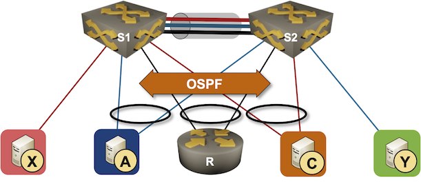
Now imagine both switches advertise the path to blue and orange subnets to the attached router. Each of them would advertise the prefix with their own IP address as the next hop, but from the router’s perspective, both next hops would be reachable over the same link (the LAG link). The router would send packets toward A or C with the destination MAC address of S1 or S2 due to layer-3 ECMP. The router would use both members of the link aggregation group (R-S1 and R-S2) links when sending those packets due to layer-2 ECMP.
According to the rules I explained in Layer-2 Flooding and Layer-3 Forwarding blog posts, a packet arriving over the peer link can never be forwarded to a dual-attached neighbor. Suppose the router decides to send a packet toward A through S1 (using the S1 MAC address) but sends the resulting Ethernet frame through the R-S2 link. In that case, S2 forwards the packet toward S1 over the peer link (due to the destination MAC address), but S1 cannot forward it to A (because it arrived over the peer link).
Regardless of the technology limitations, users love trying to implement impossible things, and the vendors usually implement all sorts of kludges to accommodate them. Can we fix the current conundrum? Of course!
While members of an MLAG cluster have independent IP addresses, most layer-3 forwarding implementations use a shared IP/MAC address as the first-hop gateway. Announcing that IP address as the third-party next hop in routing protocol updates fixes the problem for good. That’s easy to do with BGP. EIGRP and OSPF have similar functionality for external routers, but what could we do with internal routes where the routing protocol packet format does not include the next hop?
Time to get creative1. We’re facing packet drops because:
- The directly attached router selects an IP address of one of the MLAG members as the next hop.
- It rewrites the Ethernet header using the MAC address of that member as the destination MAC address.
- It sends the resulting Ethernet frame to the other MLAG member.
What if we had both MLAG members listening to both MAC addresses? That would remove the extra forwarding step over the peer link, and layer-3 forwarding would work. Unfortunately, that would also break the routing protocols – we still have to deliver unicast packets sent to the MLAG member IP address to the correct device.
Here’s a possible implementation of that final kludge2:
- Receive packets for S1 MAC, S2 MAC, and shared MAC on both MLAG members.
- Route packets for third-party destinations on the ingress MLAG member, ensuring they won’t be sent over the peer link unless necessary.
- Use policy-based routing matching on the remote MLAG member IP and MAC address to push the unicast packets for that node to the peer link without doing the L2/L3 lookup or decrementing TTL3.
Does that work? Of course. It’s also unnecessarily complex.
Long story short: Don’t run routing protocols over MLAG links. Use two independent links and two routing adjacencies.
More Information
The Data Center Network Reference Architecture part of Data Center Networking section of Data Center Infrastructure for Networking Engineers webinar describes MLAG details and typical MLAG implementations. The webinar is part of Standard ipSpace.net Subscription.
-
Also known as “Where there’s a will, there’s a way.” ↩︎
-
I’m not saying vendors are doing exactly what I’m describing. It’s just that there’s not much else they can do, and I’m pretty sure someone will quickly set me straight in the comments if I got too far into the weeds. ↩︎
-
Assuming you have good-enough ASIC and engineers programming it ↩︎
Regarding "In that case, S2 forwards the packet toward S1 over the peer link (due to the destination MAC address), but S1 cannot forward it to A (because it arrived over the peer link)."
While that is basically true(*) for bridged traffic, I see no problem to IP forward (route) an IP packet that arrived via peer link out of a local MLAG port. So while this is not optimal, it should work in general.
To make this more explicit: An Ethernet frame addressed to S1 arrives on an MLAG port of S2. S2 bridges the frame to S1. S1 conceptually receives the frame and performs an IP lookup. It then does IP forwarding (a.k.a. routing) and in principle creates a new Ethernet frame (actually re-writes the existing frame) to send towards the directly connected host A.
Technically, an ACL installed to drop bridged frames on egress on a local MLAG port needs to allow routed traffic. That could be implemented by allowing the local switch's source MAC, or via a flag set in the packet processing pipeline. I would expect that there are further implementation possibilities.
(This would affect peer link sizing, because in that situation one would expect about half the routed traffic from the router needing to traverse the peer link. Thus using a shared router MAC and so on could be used as an optimization.)
(*) In this case, i.e., when an Ethernet frame from an MLAG with an active port on the peer arrives via peer link, it must not be bridged to any local MLAG port where the peer also has an active MLAG port in the same MLAG, because then the peer has already sent the frame to those MLAGs. With individual link failures frames arriving via peer link may need to be bridged to local MLAG ports.
Yeah, I was thinking along the same lines when trying to figure out the limitations of L3 forwarding (that's why I included the link to that blog post).
Turns out that the easiest way to implement peer link filters (for bridging) is to have an egress ACL that matches on ingress interface (peer link), and the ingress interface doesn't change if the packet is routed.
Well, I know of one MLAG implementation that at first did not "support" attaching one router via MLAG to the MLAG switches and using routing protocols and L3 forwarding between router and MLAG switches. But at least one customer did that, and it worked just fine. Later this was brought to the vendor's attention, and they did not find a reason why it should not work. A bit later the vendor's documentation changed to show this as supported.
Thus I suspect that their MLAG implementation did not need any special additions.
It is sad that the vendors treat many of the MLAG implementation details as secret sauce ingredients. :-(
Yeah, you're right about the secret sauce part.
In the example you mentioned, it could be that the vendor already had to implement unicast MAC address sharing between MLAG members to support storage arrays that couldn't spell ARP -- some of them supposedly used source IP+MAC address gleaning to build fake ARP entries (that's why Nexus OS has peer-gateway command).
I just tested this in the lab (with hardware, thus ASIC based forwarding with ACLs and everything):
I then pinged A from R and checked which outgoing link was used by R (using port counters). It was the port leading directly to the next-hop, in this case S1. Thus I increased the OSPF cost for the "host" VLAN on S1, such that R changed its next-hop to S2. R still used the same local port to send the Ethernet frame to S1. The port counters indicated that the ping now went via the peer link from S1 to S2 (bridging). S2 then used IP forwarding (routing) to send the packet to the host, using the local MLAG port. The host answered via the link to S1, and S1 routed the answer via the local port to R.
I then verified via port mirror and Wireshark that the peer link indeed carried ping packets inside Ethernet frames sent from R's MAC address to S2's MAC address transported (bridged) from S1 to S2.
The little documentation there is on details of this MLAG implementation clearly states that egress ACLs are used on MLAG ports to stop frames ingressing via peer link from being flooded to local MLAG ports (unless the peer's respective ports are down).
Thus I'd say that MLAG implementations differ, and at least one works the way one might expect based on bridging and routing fundamentals.
> Thus I'd say that MLAG implementations differ, and at least one works the way one might expect based on bridging and routing fundamentals.
I can't decide whether I'm surprised or not ;)
Thanks a million for testing this!
I had only tested unicast forwarding, since that corresponds to the description in the blog post (2022-12-06 until at least now). But the problem of egress ACLs incorrectly dropping traffic might arise with IP multicast.
I do not intend to examine this case, because I have always used anycast RPs on MLAG pairs for IP multicast forwarding. This results in local forwarding in the normal case, and adjusted ACLs on link failures allow flooding in the respective failure cases.
Just don’t…