netlab VXLAN Bridging Example
netlab release 1.3 introduced support for VXLAN transport with static ingress replication. Time to check how easy it is to replace a VLAN trunk with VXLAN transport. We’ll use the lab topology from the VLAN trunking example, replace the VLAN trunk between S1 and S2 with an IP underlay network, and transport Ethernet frames across that network with VXLAN.
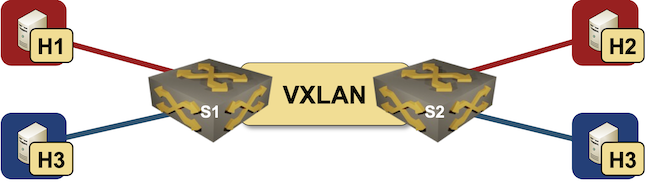
Lab topology
We still have to define the VLANs; we’ll set VLAN mode to bridge as we don’t want to do any routing between VLANs.
vlans:
  red:
    mode: bridge
  blue:
    mode: bridge
Next: nodes and links. The only difference from the VLAN trunking topology is the last link: a point-to-point IP link between S1 and S2.
nodes: [ h1, h2, h3, h4, s1, s2 ]

links:
- h1:
  s1:
    vlan.access: red
- h2:
  s2:
    vlan.access: red
- h3:
  s1:
    vlan.access: blue
- h4:
  s2:
    vlan.access: blue
- s1:
  s2:
Finally a touch of magic. We’ll deploy VLAN, VXLAN and OSPF configuration modules on the switches – and that’s it (full topology).
groups:
  hosts:
    members: [ h1, h2, h3, h4 ]
    device: linux
  switches:
    members: [ s1,s2 ]
    module: [ vlan,vxlan,ospf ]
Behind the scenes:
- OSPF configuration module starts OSPF routing process on both switches, enabling IP connectivity between their loopback interfaces (which are then used as VXLAN VTEPs).
- VLAN configuration module creates VLAN data structures and figures out that S1 and S2 need red and blue VLANs based on the VLAN access interfaces.
- By default, the VXLAN configuration module transports all local VLANs across the underlay network. You can change that behavior with vxlan.vlans list, and extend only some of the VLANs across the underlay network.
- VXLAN configuration module automatically builds per-VLAN ingress replication lists for every node using vxlan module based on which other nodes use the same VLAN. You can even define multiple VXLAN bridging domains.
Here’s a sample Arista EOS configuration generated during the netlab initial process:
hostname s1
!
spanning-tree mode mstp
!
vlan 1000
   name red
!
vlan 1001
   name blue
!
interface Ethernet1
   switchport access vlan 1000
!
interface Ethernet2
   switchport access vlan 1001
!
interface Ethernet3
   description s1 -> s2
   no switchport
   ip address 10.1.0.1/30
   ip ospf network point-to-point
   ip ospf area 0.0.0.0
!
interface Loopback0
   ip address 10.0.0.5/32
   ip ospf area 0.0.0.0
!
interface Vlan1000
   description VLAN red (1000) -> [h1,h2,s2]
!
interface Vlan1001
   description VLAN blue (1001) -> [h3,h4,s2]
!
interface Vxlan1
   vxlan source-interface Loopback0
   vxlan udp-port 4789
   vxlan vlan 1000 vni 101000
   vxlan vlan 1001 vni 101001
   vxlan vlan 1000 flood vtep 10.0.0.6
   vxlan vlan 1001 flood vtep 10.0.0.6
!
ip routing
!
router ospf 1
   router-id 10.0.0.5
   max-lsa 12000
!
end
Want to run this lab on your own, or try it out with different devices? No problem:
- Install netlab
- Download the relevant containers or create Vagrant boxes
- Download the topology file into an empty directory
- Execute netlab up -d eos -p clab if you want to run the lab with Arista cEOS in containerlab, or use whichever other device type in the
-dparameter (you can skip the-pparameter if you’re using libvirt). - Enjoy! 😊
Would this also work on bridges. For example I have devices connected to a bridge (currently macvlan) could I replace that with a vxlan to communicate to another containerlab host machine? I probably have to set the vxlans manually as I use only the netlab create command due to the big topo which is faster without ansible. But could netlab do that or only between device to another device?
So when I do it manually I probably would just use the bridge all those devices are connected to as master for my vxlan?
There's nothing in netlab (yet) that would set up that connectivity automatically, and I never tried to use a macvlan device off a bridge, but it looks like that works for you, in which case build the VXLAN connectivity between those bridges and you're done (but you'll have to do it yourself).
You could also start the (local part) of the lab in a way that the external-facing links are using Linux bridges (having three nodes attached to a link will do the trick), and then create VXLAN interface(s) and attach them to those bridges.
In any case, plenty of "manual" work until we get https://github.com/ipspace/netlab/issues/1791 implemented