Creating VRF Lite Labs With netlab
I always found VRF lab setups a chore. On top of the usual IPAM tasks you have to create VRFs, assign route targets and route distinguishers, do that on every PE-router in your lab… before you can start working on interesting things.
I tried to remove as much friction as I could with the netlab VRF configuration module – let me walk you through a few simple examples1 which will also serve to illustrate the VRF configuration differences between Cisco IOS and Arista EOS.
Single PE Router, Two VRFs
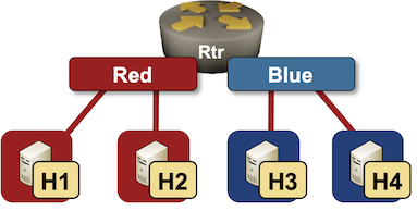
Ignoring the trivial case (single VRF, single PE-router), the next simplest possible scenario has two VRFs (red and blue) on a single PE-router:
You need just a few lines to describe the VRFs in netlab topology file:
vrfs:
  red:
  blue:
That’s it. RD and RT values are assigned automatically, and you get user-friendly names you can use in link definitions.
vrf.as global parameter which has the default value of 65000. RT/RD values for red VRF will thus be set to 65000:1.
Next, we have to define the lab devices. We’ll use Linux hosts and an Arista EOS router in the middle (the router needs VRF configuration module).
defaults.device: linux

nodes:
  rtr:
    module: [ vrf ]
    device: eos
  h1:
  h2:
  h3:
  h4:
The interesting part of the topology file is the links section where I had to specify VRFs on the PE-router connection to each link:
links:
- rtr: { vrf: red }
  h1:
- rtr: { vrf: red }
  h2:
- rtr: { vrf: blue }
  h3:
- rtr: { vrf: blue }
  h4:
And that’s it. If you have a Ubuntu host handy:
- Install netlab
- Use
netlab install ubuntu ansible containerlabto install all software packages - Install Arista cEOS container
- Copy topology file into an empty directory
- Execute
netlab up -p clab multi-vrf.ymlto start the lab (more details)
After a few minutes, you’ll have a fully configured lab – H1 will be able to ping H2, and H3 will be able to ping H4. Here’s the Arista EOS configuration generated by netlab up or netlab initial command.
vrf instance blue
   rd 65000:2
!
vrf instance red
   rd 65000:1
!
interface Ethernet1
   description rtr -> [h1] [stub]
   mac-address 52:dc:ca:fe:01:01
   vrf red
   ip address 172.16.0.1/24
!
interface Ethernet2
   description rtr -> [h2] [stub]
   mac-address 52:dc:ca:fe:01:02
   vrf red
   ip address 172.16.1.1/24
!
interface Ethernet3
   description rtr -> [h3] [stub]
   mac-address 52:dc:ca:fe:01:03
   vrf blue
   ip address 172.16.2.1/24
!
interface Ethernet4
   description rtr -> [h4] [stub]
   mac-address 52:dc:ca:fe:01:04
   vrf blue
   ip address 172.16.3.1/24
!
interface Loopback0
   ip address 10.0.0.1/32
!
ip routing
ip routing vrf blue
ip routing vrf red
!
end
If you start the lab with a router running Cisco IOS (execute netlab up -s nodes.rtr.device=csr multi-vrf.yml), you’ll get the following router configuration:
vrf definition blue
 rd 65000:2
 route-target export 65000:2
 route-target import 65000:2
 !
 address-family ipv4
 exit-address-family
!
vrf definition red
 rd 65000:1
 route-target export 65000:1
 route-target import 65000:1
 !
 address-family ipv4
 exit-address-family
!
interface GigabitEthernet2
 description rtr -> [h1] [stub]
 vrf forwarding red
 ip address 172.16.0.1 255.255.255.0
!
interface GigabitEthernet3
 description rtr -> [h2] [stub]
 vrf forwarding red
 ip address 172.16.1.1 255.255.255.0
!
interface GigabitEthernet4
 description rtr -> [h3] [stub]
 vrf forwarding blue
 ip address 172.16.2.1 255.255.255.0
!
interface GigabitEthernet5
 description rtr -> [h4] [stub]
 vrf forwarding blue
 ip address 172.16.3.1 255.255.255.0
Not too shabby for a few lines of YAML, right? But wait, it gets better…
Overlapping VPNs and VRF Route Leaking
VRFs become fun when you’re trying to implement non-trivial topologies like overlapping- or shared services VPNs. Let’s try out the simplest possible overlapping VPN topology: two hosts accessing a common server:
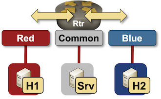
The easiest way to implement overlapping VPN topology is to play with the route targets:
- red VRF should import red and common routes
- blue VRF should import blue and common routes
- common VRF should import common, red and blue routes
Defining these requirements in netlab lab topology file is as simple as this:
vrfs:
  red:
    import: [ red, common ]
  blue:
    import: [ blue, common ]
  common:
    import: [ red, blue, common ]
As before, the system allocates RD and RT values, and you can use VRF names instead of RT/RD values to specify import route targets.
There’s nothing new in the device- and link definitions:
defaults.device: linux

nodes:
  rtr:
    module: [ vrf ]
    device: eos
  h1:
  h2:
  srv:

links:
- rtr: { vrf: red }
  h1:
- rtr: { vrf: blue }
  h2:
- rtr: { vrf: common }
  srv:
Start this lab using the same commands as before (replace multi-vrf.yml with vrf-route-leaking.yml), and you’ll get the following parameters configured on the Arista EOS router:
- VRFs are defined with
vrf instancecommands - Interfaces are assigned to VRFs
- IP routing is started in VRFs with
ip routing vrfcommands - VRF route leaking is implemented through BGP – a BGP process is started using the default
vrf.asAS number - VRFs and import/export route targets are defined in the BGP routing process
Here’s the final (VRF-related) Arista EOS configuration generated during the lab startup process:
vrf instance blue
   rd 65000:2
!
vrf instance common
   rd 65000:3
!
vrf instance red
   rd 65000:1
!
interface Ethernet1
   description rtr -> [h1] [stub]
   mac-address 52:dc:ca:fe:01:01
   vrf red
   ip address 172.16.0.1/24
!
interface Ethernet2
   description rtr -> [h2] [stub]
   mac-address 52:dc:ca:fe:01:02
   vrf blue
   ip address 172.16.1.1/24
!
interface Ethernet3
   description rtr -> [srv] [stub]
   mac-address 52:dc:ca:fe:01:03
   vrf common
   ip address 172.16.2.1/24
!
interface Loopback0
   ip address 10.0.0.1/32
!
ip routing
ip routing vrf blue
ip routing vrf common
ip routing vrf red
!
mpls ip
!
router bgp 65000
   vrf blue
      rd 65000:2
      route-target import vpn-ipv4 65000:2
      route-target import vpn-ipv4 65000:3
      route-target export vpn-ipv4 65000:2
      router-id 10.0.0.1
      redistribute connected
   !
   vrf common
      rd 65000:3
      route-target import vpn-ipv4 65000:1
      route-target import vpn-ipv4 65000:2
      route-target import vpn-ipv4 65000:3
      route-target export vpn-ipv4 65000:3
      router-id 10.0.0.1
      redistribute connected
   !
   vrf red
      rd 65000:1
      route-target import vpn-ipv4 65000:1
      route-target import vpn-ipv4 65000:3
      route-target export vpn-ipv4 65000:1
      router-id 10.0.0.1
      redistribute connected
It’s interesting to compare Arista EOS VRF route leaking configuration with Cisco IOS one:
- Import/export route targets are defined in
vrf definitionon Cisco IOS. They are defined withinvrfsection ofrouter bgpconfiguration on Arista EOS. - IPv4/IPv6 address families have to be configured within a
vrf definitionon Cisco IOS.ip routinghas to be configured for each VRF on Arista EOS. - VRFs are defined as
address-familywithin a BGP process on Cisco IOS. Arista EOS usesvrfsections withinrouter bgpconfiguration.
vrf definition blue
 rd 65000:2
 route-target export 65000:2
 route-target import 65000:2
 route-target import 65000:3
 !
 address-family ipv4
 exit-address-family
!
vrf definition common
 rd 65000:3
 route-target export 65000:3
 route-target import 65000:1
 route-target import 65000:2
 route-target import 65000:3
 !
 address-family ipv4
 exit-address-family
!
vrf definition red
 rd 65000:1
 route-target export 65000:1
 route-target import 65000:1
 route-target import 65000:3
 !
 address-family ipv4
 exit-address-family
!
interface Loopback0
 ip address 10.0.0.1 255.255.255.255
!
interface GigabitEthernet2
 description rtr -> [h1] [stub]
 vrf forwarding red
 ip address 172.16.0.1 255.255.255.0
!
interface GigabitEthernet3
 description rtr -> [h2] [stub]
 vrf forwarding blue
 ip address 172.16.1.1 255.255.255.0
!
interface GigabitEthernet4
 description rtr -> [srv] [stub]
 vrf forwarding common
 ip address 172.16.2.1 255.255.255.0
!
router bgp 65000
 bgp log-neighbor-changes
 !
 address-family ipv4 vrf blue
  redistribute connected
 exit-address-family
 !
 address-family ipv4 vrf common
  redistribute connected
 exit-address-family
 !
 address-family ipv4 vrf red
  redistribute connected
 exit-address-family
Told you – labbing VRFs has never been easier ;)
Build Your Own
You’ll find the lab topology files on GitHub. To use them:
- Install netlab and your preferred lab environment. These days I find it easiest to use Arista cEOS with containerlab.
- Copy topology files into an empty directory
- Execute netlab up with the parameters described above.
-
Yes, I’m a fanboy, but it’s a great tool ;) ↩︎