Multi-Chassis Link Aggregation (MLAG) and Hot Potato Switching
There are two reasons one would bundle parallel Ethernet links into a port channel (official term is Link Aggregation Group):
- Transforming parallel links into a single logical link bypasses Spanning Tree Protocol loop avoidance logic; all links belonging to the port channel can be active at the same time (see also: Multi-Chassis Link Aggregation basics).
- Load sharing across parallel links in a port channel increases the total bandwidth available between adjacent L2 switches or between routers/hosts and switches.
Ethan Banks wrote an excellent explanation of traditional port channel caveats (proving that 1+1 sometimes does not equal 2); things get way worse when you start using Multi-Chassis Link Aggregation due to hot potato switching (the switch tries to forward packets toward destination MAC address as soon as possible) used by all MLAG implementations I’m familiar with.
What Is Hot Potato Switching?
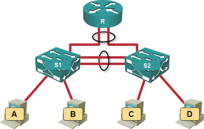
Hot potato switching is a very simple principle (try to get rid of the packet as soon as possible) best explained with a few examples. Let’s start with a very simple architecture: a router connected to two switches (MLAG cluster) through a link aggregation group, and a bunch of servers with a single uplink per server (ESXi hosts usually look that way even when they have redundant uplinks).

A simple data center fabric
When the router needs to communicate with server A, it sends an ARP request. Let’s assume the ARP request goes over the R–S2 link and is then flooded across S2–S1 and S1–A links (as well as a few other links). At this moment all switches know where R is.
When A replies to R, the switches forward packet based on their MAC address tables. Without modifying the MAC learning process, the return packet would go from A through S1 and S2 to reach R (and all the subsequent traffic could flow over the same link) – clearly a suboptimal traffic flow that places unnecessary load on the inter-switch link.
Every decent MLAG implementation thus has to modify the MAC learning process: as soon as a new source MAC address is seen in a packet arriving through a port belonging to a port channel, the MAC reachability information is propagated to all other members of the “stack” and they use their local ports in the same port channel to forward the traffic toward the newly-discovered MAC address.
Architectures supporting more than two nodes in a MLAG group might have to run a routing protocol internally and forward the packets toward the closest port in the port channel. Juniper is (according to the presentation they gave us at Net Field Day) running IS-IS between members of their “distributed stack”. Alternative architectures that lobotomize all but one control plane are simpler: the single active control plane modifies MAC address tables in all switches.
With the modified MAC learning rules, the entry for MAC address R in S1 points to the port in the port channel toward R, not to the inter-switch link and the traffic from A to R flows over the shorter path A–S1–R. As you can see, the switches successfully got rid of the hot potato (= the packet) without warming the inter-switch link.
Load Balancing Implications
To make the long story short (more in a follow-up post): if servers A and B decide to send data to R concurrently, there’s no way to split that load across the links in the port channel between R and S1+S2.
More Information
- Multi-chassis Link Aggregation (and numerous other LAN, SAN and virtualization technologies) is described in the Data Center 3.0 for Networking Engineers webinar.
- The term hot potato routing is commonly used in Internet to describe a routing strategy where an ISP sends the packets into adjacent autonomous systems as soon as possible.

Thanks
MB
Very interesting insight. The MC-LAG implementation I've been privy to (ALU TiMOS) does not use load balancing - you always have one or more active and one or more standby group members, with active members always being on the same physical chassis and standby being on the other. While this solution potentially has a disadvantage of not using all the available bandwidth (and yes, potentially using a sub-optimal path for some flows), it on the other hand has an advantage of simplicity (and thus being inherently more stable due to fewer things that could go wrong) and lack of the problem you're describing.
Cross-chassis load balancing, that is.
I'm thinking of a 3750 Stack at each datacenter, connected through 2 SFP GB links, bundled each Uplink at one chassis, so there can fail one catalyst or line without big trouble.
Speaking to Ivan's example specifically, in a 3750 cross-stack etherchannel, I believe you would see a more balanced use of the cross-stack links. In other words, if servers A & B are uplinked to the same 3750 switch in a stack, the stack would still use all members of the cross-stack etherchannel in accordance with the port-channel load-balancing algorithm you had selected.
I'll admit this is based purely on my experience managing a couple of hundred 3750 stacks, where we relied on cross-stack etherchannel both for performance and resiliency. We saw good, load-balanced results across the links hashing on port numbers inbound from the agg/core layer, and on source/destination IP outbound from the stack (which doesn't support hashing on L4 port numbers). The load-balancing method appropriate for your stacks might vary depending on your layout.
Someone who's dug deeper into 3750 control-plane logic will correct me if I'm misunderstanding what's really going on there.
could we do that with only two edge network L2 (Juniper ex series) switches and how the router will act if it connect to an external network with out needing to run STP?