Category: WAN
Multilink bundles have varying bandwidth
I have always intuitively assumed that the interface bandwidth on MLPPP bundles is the sum of interface bandwidths of individual interfaces that are part of the bundle. Recently I’ve tested my assumption and it works as expected.
PPP default route
You do not need the route "ip route 0.0.0.0 0.0.0.0 Dialer0 10 track 100" and the tracking if you configure "ppp ipcp route default" on the dialer interface. Works the same way... :-)You might be wondering why Cisco's engineers decided to pollute IOS with yet another feature. The problem they had was the way PPP over Frame Relay is implemented: it uses virtual interfaces and although you have a very static connection, you cannot bind a static interface name to it. A dynamic interface (with potentially changing name) is cloned from the virtual template every time the PPP-over-Frame-relay session is started. Obviously you cannot configure a static default route pointing to it in advance, so you need yet another feature to do it (I'll not even try to figure out how to create non-default static routes pointing to cloned interface).
The Impact of tx-ring-limit
Setting the size of the hardware output queue in Cisco IOS with the (then undocumented) tx-ring-limit (formerly known as tx-limit) has been a big deal when I was developing the first version of the QoS course that eventually became the initial release of the Implementing Cisco Quality of Service training.
However, while it's intuitively clear that the longer hardware queue affects the QoS, years passed before I finally took the time to measure the actual impact.
Almost-Dynamic Routing over ADSL Interfaces
Recently I had to implement Internet access using ADSL as the primary link and ISDN as the backup link. Obviously the most versatile solution would use the techniques described in my Small Site Multi-homing articles, but the peculiarities of Cisco IOS implementation of the ADSL technology resulted in a much simpler solution.
IOS implementation of PPPoE links uses dialer interfaces. However, the “dialing” on these interfaces is activated as soon as the underlying PPPoE session is active (before the first interesting packet is routed to the interface). When the simulated dial-out occurs, the router starts PPP negotiations including the IPCP handshake, which usually results in an IP address assigned to the dialer interface. Net result: if the dialer interface has an IP address, the PPPoE session is obviously active (and vice versa).
WAN IP addresses and subnet masks
“What I would like to know is, on my PPP negotiated ADSL connection, how the ISP assigns me a /32 ip address.”… which prompted me to test various WAN encapsulations and address assignment rules. Here are the results:
- On all WAN encapsulations you can configure subnet masks down to /31 (/30 in old IOS releases).
- The same IP address can be used on more than one interface as long as both IP address and subnet mask match.
- Two WAN interfaces can have different IP addresses but still belong to the same IP subnet. You would use this on Frame Relay when you have multiple interfaces into the same FR cloud for bandwidth reasons.
- If you configure IP address with IPCP (with the ip address negotiated command), the subnet mask becomes /32 as IPCP does not carry subnet mask (and you get the host route toward the PPP peer unless you turn off the PPP peer route option)
- If you configure IP address with SLARP (Serial Line ARP) on HDLC, the subnet mask is inherited from the peer (HDLC SLARP carries subnet mask) and the IP address is determined by flipping the low-order bits in the neighbor's IP address.
Reduce IP addressing errors in lab environment
hostname Core-2… and use IPCP negotiation on the POP router to pick up the WAN IP address:
!
interface Serial1/0
description link to POP
ip address 10.0.2.1 255.255.255.252
encapsulation ppp
peer default ip address 10.0.2.2
hostname POP
!
interface Serial1/0
 description link to Core-1
 ip address negotiated
 encapsulation ppp
You should not configure no peer neighbor-route on the router that gets dynamic IP address, as the subnet mask is not assigned with IPCP; you need the IPCP-generated host routes if you want to do hop-by-hop telnet between the routers.
Remove unwanted PPP peer route
WAN emulation toolkit
Making the case for Layer 2 and Layer 3 VPNs
Occasionally someone would try to persuade me that the layer-2 VPN services are like aspirin (you know, totally harmless plus it could get rid of all your headaches). OK, that might be true if you take the layer-2 VPN offering as a pure transport solution and plug in an extra router (sometimes also called a layer-3 switch by marketing people) between the Service Provider’s Ethernet (or whatever they give you) and your LAN. But there are people who don’t know the details and plug the SP Ethernet straight into their L2 switch … and things might even work for a while … until the whole network collapses.
In my opinion, we need both L2 and L3 VPN services, but it’s important that they are positioned and deployed correctly. You can read more about my views on this topic in the SearchTelecom article Making the case for Layer 2 and Layer 3 VPNs.
Configure DNS Servers Through IPCP
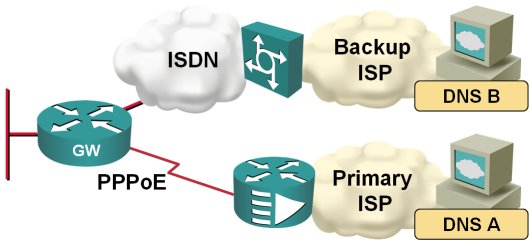
After I've fixed the default routing in my home office, I've stumbled across another problem: the two ISPs I'm using for my primary and backup link have DNS servers that reply solely to the DNS requests sent from their own IP address range:

When the traffic is switched from the primary to the backup ISP, I therefore also need to switch the DNS servers. Fortunately, this is quite easy to do on a router; you just need to configure ppp ipcp dns request on the dialer interface and the router starts asking for the DNS server address as part of the IPCP negotiation.
Install default route with PPP
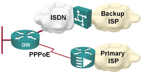
In my home office, I'm using DSL access to the Internet with ISDN backup to another ISP, as shown on the next figure:

Obviously, I would like the ISDN backup to kick in whenever the primary connection goes down; two static default routes and reliable static routing on the primary default seem like a perfect solution.
Emulate dialup links with serial lines
interface Serial1/0… and this is the “server”-side configuration:
ip address negotiated
encapsulation ppp
ppp authentication pap optional
ppp pap sent-username client password 0 client
interface Serial1/0To trigger PPP negotiations, shut down and re-enable the serial interface on either side.
ip address 10.0.0.33 255.255.255.252
encapsulation ppp
peer default ip address 10.0.0.34
ppp authentication pap callin
!
username client password client
Note: As I'm using PAP authentication, I could use the more secure username secret configuration command, which would not work with CHAP.
Ones Are Slower than Zeroes
Thinking about the implications of bit stuffing I wrote about in the SDLC post, I realized that long sequences of ones would be transmitted slower than long sequences of zeroes due to an extra bit being inserted after every fifth consecutive one. The theory would predict a 20% decrease in transmission speed.
Of course I wanted to test this phenomenon immediately. I connected two routers with a low-speed (64 kbps) link, and started a series of pings. Not surprisingly, the results confirmed the theory:
Back to the roots: it all started with SDLC
IBM obviously also had problems with bad modems and solved it with the NRZI encoding that was part of SDLC standard (and a major pain in the good old days when the appliques on the old Cisco routers did not support it and we've been trying hard to penetrate IBM accounts). You can still configure NRZI encoding on most routers' serial links (it might depend on the actual hardware platform) with the nrzi-encoding interface configuration command (you had to do it with jumpers in the AGS+). Incidentally, changing interface encoding to NRZI was really helpful when you had to break things in the preparation for the troubleshooting part of the original CCIE lab).
Enough theory, let's summarize the proposed solutions:
- The nrzi-encoding (if available) is the best one, as it reliably solves the problem, is transparent and does not incur additional overhead.
- Compression or encryption are OK, but they result in significant CPU overhead (unless you have hardware encryption/compression modules) and might (at least in theory) still produce a long sequence of zeroes, although with a very low probability. IPSec also introduces overhead due to additional IPSec headers.
- LFI (effectively multilink PPP over a single link) is also a good solution, as the PPP framing and MLPPP headers break the long sequences of zeroes (you might have to fine-tune the fragment size with ppp multilink fragment size configuration command), but it introduces overhead on the WAN link.
- IP fragmentation would work, but would be quite bandwidth-consuming. If the fragmentation would be performed by the router, the overhead would be 20 bytes per fragment (IP header), if the sending host performs the fragmentation, the overhead is 40 bytes per fragment for TCP sessions. For example, if we reduce the IP MTU size to 256 bytes, the TCP session overhead is over 18% (and we were scoffing at the ATM designers that made us live with 10% overhead).
- The invert data command would only help if the modem has problems with long strings of zeroes, not with long strings of the same value.
- The tunnel key command just sets a 4-byte field in the GRE header but does not affect the encapsulated data at all.
React to excessive jitter with EEM
William Chu sent me a working configuration he uses to measure jitter with the IP SLA tool and react to excessive jitter on the primary link. First you have to create the jitter probe with the IP SLA commands:
ip sla monitor 3000
 type jitter →
   dest-ipaddr 199.11.18.168 dest-port 12333 →
   source-ipaddr 199.11.18.169 codec g729a →
   codec-numpackets 100
 tos 184
 frequency 10
Note: The continuation character (→) indicates that the configuration command spans multiple lines
Next you have to define the IP SLA reaction to excessive jitter. William configured his router to react when the jitter exceeds 300 milliseconds and returns back to normal when the jitter falls below 290 milliseconds (some hysteresis is always a good thing).
ip sla monitor reaction-configuration 3000 →
  react MOS threshold-value 300 290 →
  threshold-type consecutive →
  action-type trapOnly
As the last step in the SLA configuration, you have to start the probe:
ip sla monitor schedule 3000 →
  life forever start-time now
After the SLA probe and out-of-bounds reaction have been configured, the router will generate syslog messages whenever the jitter gets above the threshold as well as when it falls below the second threshold. You can then use the EEM applets to act on the syslog messages:
event manager applet MOS-Below
 event syslog occurs 1 period 120 →
   pattern "Threshold below for MOS"
 ... actions ...
!
event manager applet MOS-Above
 event syslog occurs 1 period 120 →
   pattern "Threshold exceeded for MOS"
 ... actions ...
