Multi-Layer Switching and Tunneling
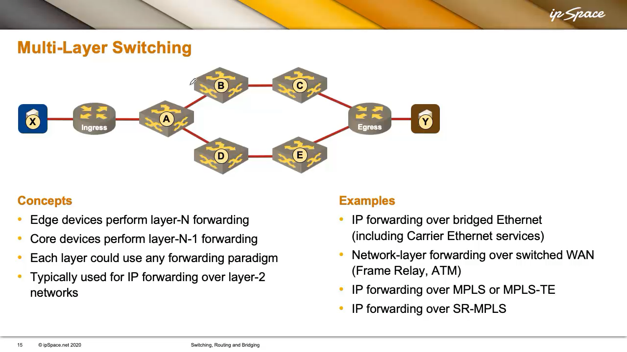
When deep-diving into the confusing terminology of switching, routing, and bridging, I mentioned you could perform packet forwarding at different layers of a networking stack. In this blog post, we’ll explore what happens when we combine packet forwarding on multiple layers within a single network, resulting in multi-layer switching, where edge devices perform Layer n forwarding (usually Layer 3), and core devices perform Layer n-1 forwarding (typically Layer 2).
Each layer can use any forwarding paradigm you choose. However, since we generally use IP at Layer 3, edge devices typically perform hop-by-hop destination-based forwarding, while core devices can use alternative methods.
For example, you can do IP forwarding over bridged Ethernet. In that setup, the ingress router, the egress router, and all devices in between form a single Ethernet network—say, a carrier Ethernet service. Devices in the network core forward packets based on destination MAC addresses. The ingress router must thus know how to reach the egress router’s MAC address (or multiple addresses, for redundancy or load balancing).
In the past, when WAN services used virtual circuits, someone had to establish a virtual circuit from the ingress to the egress router (multiple circuits can be used for load balancing). The ingress router maintained a mapping table, like “egress router reachable over virtual circuit 1” or “the same router is also reachable over virtual circuit 2.”
After setting up the mapping table, the ingress and egress routers would run a routing protocol over these circuits to exchange information about endpoints like X and Y. That way, they could forward packets across the network.
We’re still using a similar paradigm today when we combine IP forwarding with MPLS or MPLS-TE (often running BGP between ingress and egress routers). In these cases, the routers effectively create virtual circuits, either with LDP in MPLS or via traffic-engineered tunnels in MPLS-TE. The ingress router somehow requests a circuit to the egress router (or builds one based on already-available information), and one gets set up1. The ingress router then uses those circuits to send traffic to the egress router2.
You can also achieve similar outcomes with segment routing, which is just source routing in disguise. In the Segment Routing model, the ingress router must know the path to the egress router, such as via nodes A, B, and C (or an alternate path via A, D, and E). The ingress router then prepends the desired path across the network to the packet it wants to forward, and the intermediate routers follow the instructions to deliver the packet across the network.
The ingress router can learn the path to the egress router by participating in a routing protocol (standard routing protocols have been extended to carry segment routing information) or via a centralized controller, commonly referred to as an SDN controller by vendor marketing departments. The SDN controller tells edge routers what labels (segments) to use to reach specific destinations3.
Tunneling
So far, we discussed a scenario in which core devices performed forwarding on a networking layer below the one used by the edge devices, but what happens if the edge devices perform Layer n forwarding, and core devices perform Layer n or even higher-layer forwarding? Welcome to the confusing world of tunneling, often used to do Layer 2 (Ethernet) forwarding across Layer 3 (IP) networks.
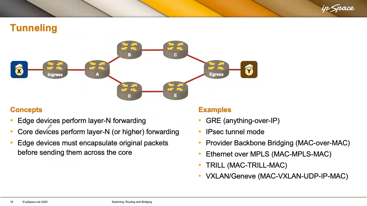
In such cases, edge devices must encapsulate the original packet. In the case of Ethernet-over-IP forwarding, the envelope includes a destination IP address, an inner MAC header, and an outer MAC header, because the routers still need MAC addresses on Ethernet links. Ultimately, you end up with a Layer 2 header buried within another Layer 2 header—hence, tunneling (example).
Examples include:
- GRE, which can carry anything over IP.
- IPsec tunnel mode, which wraps an IP packet inside an IPsec packet, then adds another IP header on top.
- Provider Backbone Bridging (PBB), which wraps one MAC header inside another.
- TRILL, which is similar but uses a slightly different header.
- Ethernet over MPLS, where a MAC frame is encapsulated with MPLS labels and then an outer MAC frame.
- VXLAN or Geneve, where an Ethernet frame is wrapped with a VXLAN/Geneve header, then a UDP header (to avoid confusing middleboxes), then another IP header and MAC header.
All of this is done just to make it appear as if a single Ethernet cable connects X and Y. I know it sounds weird, but networking vendors love to sell expensive complex solutions.
Loose Source Routing
As always, there are hybrid approaches, such as loose source routing. In source routing, the sender (X) specifies the path to the destination (Y). But what if the network already uses hop-by-hop forwarding and knows how to get from X to Y?
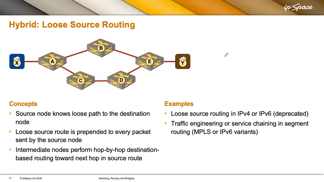
Loose source routing allows X to say, “I want this packet to go to Y, but I want it to pass through D first.” X doesn’t need to know the full path—it doesn’t need to know about node C at all. Everyone just forwards the packet to D. When D receives it, it finds another packet inside—this one destined for Y. D knows how to reach Y (maybe via E) and forwards it accordingly.
That’s how loose source routing works in IPv4 or IPv6. It’s also similar to how traffic engineering or service chaining works in segment routing.
In both MPLS and IPv6-based segment routing, each node has global and local labels. Say node D has a global label D, and everyone knows what the label D means. X takes an IP packet for Y, adds label D on top, and sends it. The network delivers it to D, where the label is stripped, and the remaining IP packet is forwarded—either directly to Y or with another label for E, which forwards it to Y.
Summary
The Forwarding Packets Across a Network blog post introduced three major forwarding paradigms:
- Source routing
- Virtual circuit-based forwarding
- Hop-by-hop destination-based forwarding
These can be combined in multi-layer switching or tunneling. You can also create hybrids like loose source routing.
Q&A Section
Question from Dan (regarding multi-layer switching):
Do both ingress and egress routers have the same virtual circuit ID, or is it local-only?
In most implementations, the virtual circuit ID is local. There are two aspects to consider:
- Circuit ID: Is it the same at both ends?
- Circuit directionality: Are we talking about one circuit or two?
Typically, the circuit ID is not the same on both ends. This is partly due to the limited address space for circuit IDs. For example, Frame Relay used 10-bit IDs. MPLS uses 20-bit labels, but in practice, platforms can’t handle the full range of label values. Traditional MPLS implementations thus conserve label space by using local IDs, such as “circuit 1” on one side and “circuit 2” on the other (SR-MPLS uses global labels).
As for the second point: in older WAN technologies like Frame Relay, ATM, or X.25, circuits were bidirectional, inspired by voice calls—like when one person calls another, both can talk without needing a second call.
In MPLS, however, circuits are unidirectional. If an ingress router wants a traffic-engineered tunnel to an egress router, it sets up a unidirectional tunnel. For the return traffic, the egress router must set up a separate tunnel back to the ingress router. Each tunnel is assigned a different circuit ID.
On Label Swapping in MPLS Networks
Label swapping in MPLS networks resembles MAC address swapping in Ethernet/IP networks, but with key differences.
In IP forwarding, a packet arrives with a destination IP and a MAC header. The MAC header is discarded, as it only facilitates the packet’s delivery to the current hop. The router looks up the destination IP, finds the next hop (say, B), determines B’s MAC address, builds a new MAC header, and sends the packet.
So it seems like MAC addresses are being “swapped,” but actually:
- The old MAC address is discarded.
- The routing lookup uses the destination IP address, not the MAC address.
- A new MAC header is built for the next hop.
In MPLS, X sends a packet to Y with label L1 (assigned by A). Router A has a table mapping L1 to L2, the label that router B instructed router A to use. So A swaps L1 for L2 and forwards the packet.
Key differences:
- Lookup is done on the label (L1), unlike IP forwarding, where it’s on the IP address.
- Only the top label is swapped; deeper labels remain.
- The IP header isn’t examined at all.
To summarize: in virtual circuit-based forwarding, routers swap the circuit ID, while in IP routing, they discard Layer 2 headers, do another network-layer lookup, and create a new Layer 2 header.
Next: Finding End-to-End Paths: Topology and Endpoints Continue
-
The ingress router can even request multiple circuits for the same destination. ↩︎
-
It’s worth noting that the MPLS virtual circuits are unidirectional. The egress router has to set up an independent virtual circuit toward the ingress router to forward the return traffic. ↩︎
-
Segment routing can use MPLS labels (SR-MPLS) or IPv6 addresses (SRv6). ↩︎