In September 2020, I created the Getting Packets Across the Network video as part of the How Networks Really Work webinar. This blog post is a Whisper transcript edited by ChatGPT and polished by Yours Truly ;)
ChatGPT did a decent job editing the transcript, but I wonder how far it pushed it toward the AI slop. Your comments are highly appreciated. Thank you!
Forwarding Packets Across a Network
After inspecting the confusing bridging/routing/switching terminology and a brief detour into the control/data plane details, let’s talk about how packets actually move across a network.
As always, things were simpler when networks were implemented with a single cable. In that setup, all nodes were directly reachable, and the only challenge was figuring out the destination node’s address; it didn’t matter whether it was a MAC address, an IP address, or a Fiber Channel address. On a single cable, you could just broadcast, like, “Who has this service?” and someone would reply, “I’m the printer you’re looking for.” That’s how many early non-IP protocols operated.
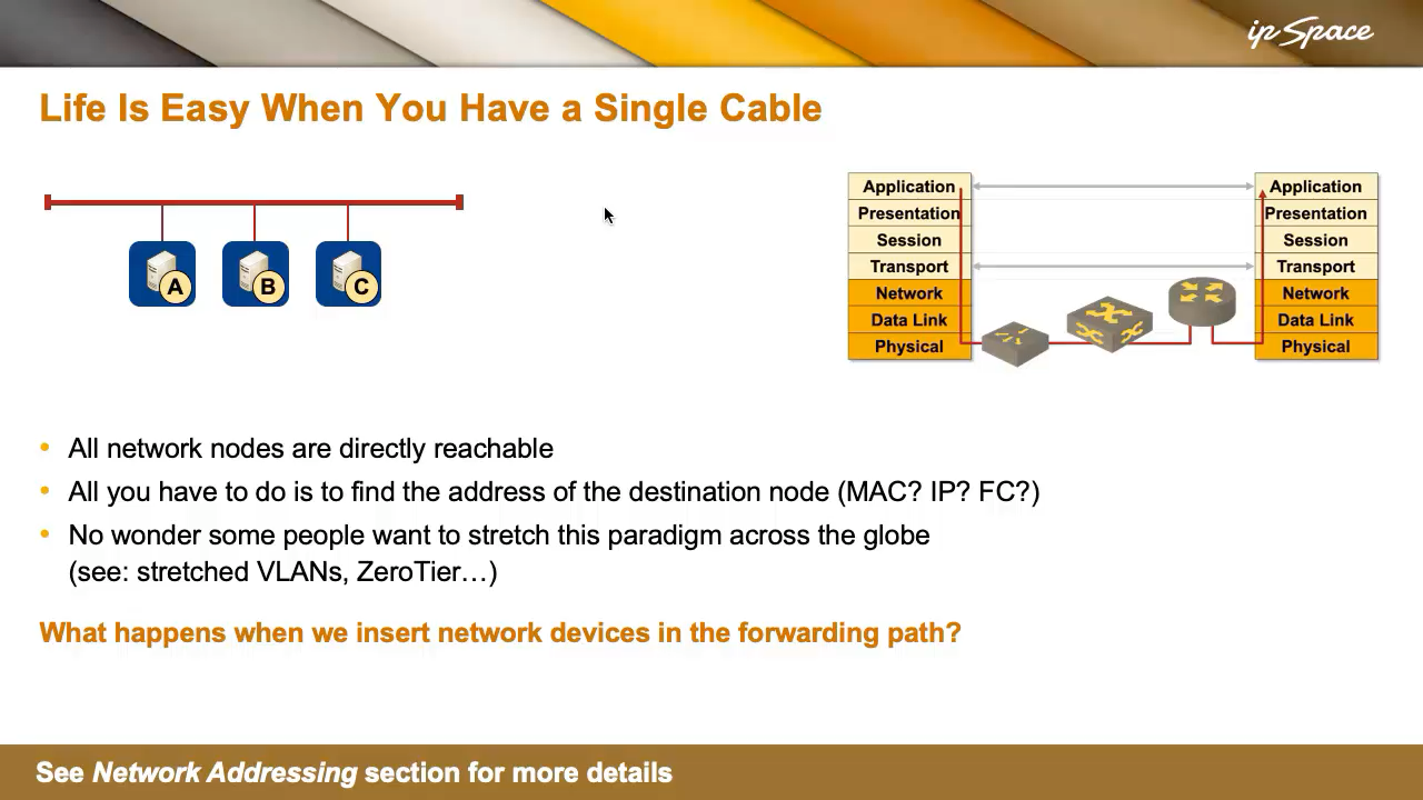
Life on a single cable was straightforward. You just plugged things in, and it all worked—until it didn’t. No wonder some folks wanted to stretch that simplicity across the globe, resulting in vendors singing the praises of stretched VLANs, and Thought Leaders telling you how to extend a VLAN into the public cloud. Some VPN vendors even simulate bridging over a VPN. But let’s not dive into the implications of that just yet—we’ll come back to it when discussing routing versus bridging.
The topic of this blog post is simpler: what happens when we break that single cable into two and insert a network device in the forwarding path? How do we still get packets from A to B now that there’s something in the middle?
Three fundamental technologies can make that happen, and we’ll examine them using a simple network from the following diagram.
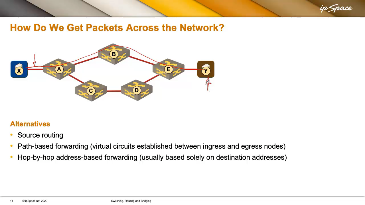
Suppose X is trying to reach Y. X can reach Y via two possible paths: A-B-E or A-C-D-E. So someone has to decide which path to use. These are the commonly used options:
-
Source Routing: X (through some unspecified mechanism) figures out its packets have to pass through A, B, and E to reach Y.
-
Path-Based Forwarding (Virtual Circuits) Someone could set up a virtual link (or circuit) between X and Y and tell X: “If you want to send packets to Y, just use this virtual circuit.” Virtual circuits are equivalent to phone calls: you dial the number, a connection is made, and you start talking1.
You could say, “Isn’t that what TCP does today?” and you’d be right. But in the old days, virtual circuits were the only way to communicate—until IP came along and said, “Forget phone calls. Networking should be more like parcel delivery.”
-
Hop-By-Hop Destination-Only Forwarding Imagine X is Amazon, and Y is you at home, out of toilet paper. You order some, specify your address, and Amazon puts together a packet and sticks your address on it. The packet gets passed from one delivery person to the next, with each one checking the address and forwarding it independently. That’s how IP forwarding works: hop-by-hop, with each device making an independent forwarding decision based only on the destination address.
Source Routing
The easiest forwarding mechanism is source routing (more precisely, strict source routing), where the source node knows the full path to the destination. We’re not yet asking how the source node gets this information (we’ll get to that later); we’re just focusing on forwarding right now.
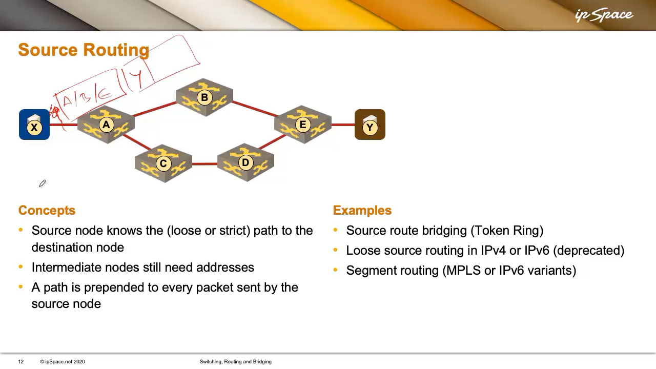
So, the source (X) knows the path to the destination (Y): through A, B, and E. Intermediate nodes might only know the next hop—A might know where B is, but not E. So, X prepends a routing header to each packet: “This has to go through A, B, E.” Every packet gets this routing header.
An interesting side effect is that X can use both paths: it might send some packets via A-B-E and others via A-C-D-E. It could even select the path based on traffic type—voice over one path, web traffic over the other. The decision is entirely up to X.
This idea was first used by IBM in Token Ring networks with Source Route Bridging, where small rings were connected by bridges. The source nodes specified the full path to the destination, listing all bridges and rings along the way.
Something similar existed in both IPv4 and IPv6. It was later deprecated (which in IETF-speak means “we hope it dies, but it probably won’t”) due to serious security risks. For example, an attacker could spoof being a trusted node and use a source routing header to sneak traffic through unauthorized paths. That’s why IPv4 source routing was disabled, and IPv6 followed suit years later with strong deprecation language: nodes must not recognize source routing headers.
Of course, bad ideas never really die; they just get reinvented. Enter segment routing, which has two flavors:
- MPLS-based segment routing uses MPLS labels to guide packets along a specific path. It’s a fairly reasonable idea and widely used.
- IPv6-based segment routing uses IPv6 addresses instead of labels. It reintroduces some of the same spoofing concerns, though proponents claim security through digital signatures. Not everyone is convinced, and real-world deployments are limited.
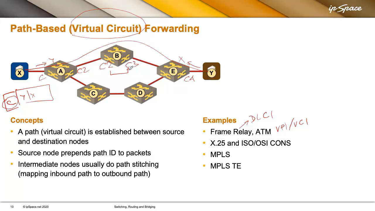
Virtual Circuit-Based Forwarding
When networking was new in the ’70s, people thought in terms of voice calls, resulting in technologies that (just like a phone call) established a virtual circuit between two endpoints before sending data.
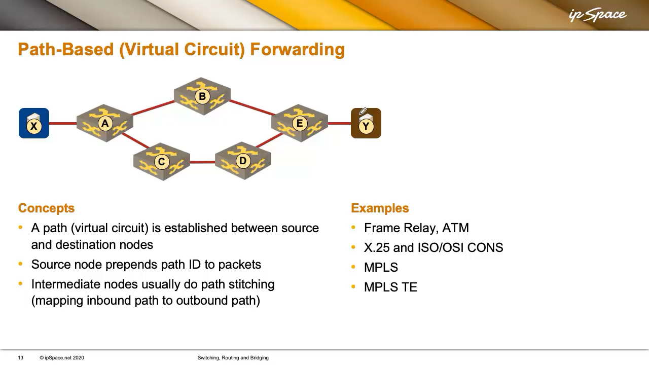
X wants to talk to Y, so a virtual circuit is set up (using a signalling protocol, a central controller, or manual configuration), and every intermediate node knows about it. X then sends packets with a circuit ID instead of a destination address. The virtual circuit ID was called DLCI in Frame Relay, and Virtual Path/Virtual Circuit identifier (VPI/VCI) in ATM.
Bandwidth was expensive in the heyday of switched WAN technologies, so we wasted as few bits as possible on the virtual circuit identifiers. They were usually locally significant (sometimes even limited to a single interface), and the intermediate nodes would build end-to-end circuits by mapping inbound circuit identifiers into next-hop identifiers. For example, A would tell X to use circuit identifier C, A would map it to C2, B to C3, and so on. Each node would maintain a local mapping (e.g., C2 → C3), much like MPLS does today.
Hop-by-Hop Forwarding
This is the forwarding method most modern networks use. Each router or switch knows how to reach all destinations, or uses a default route toward a node with more granular information. Every device makes an independent decision based solely on the destination address. In our network, X can’t control how A forwards the packet to Y.
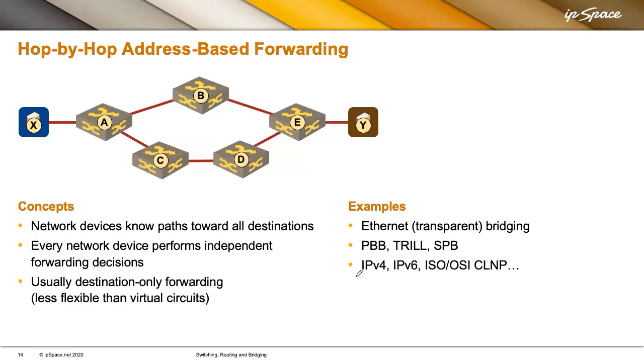
The independent local decisions make hop-by-hop forwarding less flexible than virtual circuits. In a virtual-circuit world, X could choose which path to use. In a network using hop-by-hop forwarding, X has no influence on the forwarding path. If A thinks B is the best next hop, X can’t change that, even if a better path exists via C and D.
Technologies using this model include:
- IPv4 and IPv6
- CLNP (for the three people still running OSI to manage their SONET/SDH gear)
- Transparent bridging
- More advanced bridging protocols like Provider Backbone Bridging (PBB), TRILL, and SPB
Next: Multi-Layer Switching and Tunneling Continue
-
These days, a phone call might be a VoIP session; in the past, it was a physical circuit made with relays, or a time-division multiplexed bit stream. The implementation may vary, but the principle is the same: establish a dedicated path before communication starts. ↩︎
I appreciate all these blog posts which are derived from your courses or webinars. Missed the window to subscribe in the past. Cheers!