EIGRP Third-Party Next Hops
EIGRP routing updates have always contained the next hop field (similar to BGP updates), which was unused until Cisco IOS release 12.3 when the no ip next-hop-self eigrp AS-number interface configuration command was implemented.
EIGRP does not set the next hop field by default. An EIGRP router receiving a routing update thus assumes that the next hop of the received routes is the sending router. This behavior usually works well, but prevents site-to-site shortcuts to be established in DMVPN networks, and results in suboptimal routing in some route redistribution scenarios.
With the no ip next-hop-self eigrp command configured on an interface, an EIGRP router will set the next hop field in outgoing routing updates if the IP next hop in its EIGRP topology table belongs to the IP subnet of the outgoing interface. The next hop field is set in internal as well as external EIGRP routing updates, optimizing traffic flow in route redistribution scenarios.
NBMA Network with Default EIGRP Next-Hop Processing
The default EIGRP next hop processing will be illustrated in a simple NBMA network with three routers. R1 is the hub router; R2 and R3 are spoke routers. The examples use Frame Relay network between them; it could also be a DMVPN Phase-1 network or a Carrier Ethernet service.
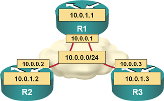
NBMA network diagram
EIGRP split horizon has been disabled on R1 to allow route propagation between R2 and R3. The relevant parts of the R1’s router configuration are included in the following printout:
interface Serial1/0
 description Link to FR
 ip address 10.0.0.1 255.255.255.0
 encapsulation frame-relay
 no ip split-horizon eigrp 1
 frame-relay lmi-type ansi
By default, R1 does not set the next hop field in outgoing EIGRP routing update:
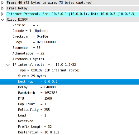
EIGRP does not set the next-hop field by default
After the EIGRP adjacencies are established, the routing table on R3 contains routes to loopback interfaces of R1 and R2. The next-hop field in the EIGRP updates sent by R1 was empty; the next hop of both routes in the R3’s routing table is thus R1.
R3#show ip route | begin Gateway
Gateway of last resort is not set

     10.0.0.0/8 is variably subnetted, 5 subnets, 2 masks
C       10.0.1.3/32 is directly connected, Loopback0
S       10.0.0.2/32 [1/0] via 10.0.0.1
D       10.0.1.2/32 [90/2809856] via 10.0.0.1, 00:05:37, Serial1/0
D       10.0.1.1/32 [90/2297856] via 10.0.0.1, 00:05:37, Serial1/0
C       10.0.0.0/24 is directly connected, Serial1/0
The EIGRP topology table printout displays the EIGRP vector metric and next hop details. As expected, the bandwidth of both routes is the same, but the delay and the hop-count of R2’s loopback interface have been increased as the routing update has passed through R1.
R3#show ip eigrp topology 10.0.1.1 255.255.255.255
IP-EIGRP (AS 1): Topology entry for 10.0.1.1/32
  State is Passive, Query origin flag is 1, 1 Successor(s), FD is 2297856
  Routing Descriptor Blocks:
  10.0.0.1 (Serial1/0), from 10.0.0.1, Send flag is 0x0
      Composite metric is (2297856/128256), Route is Internal
      Vector metric:
        Minimum bandwidth is 1544 Kbit
        Total delay is 25000 microseconds
        Reliability is 255/255
        Load is 1/255
        Minimum MTU is 1500
        Hop count is 1
R3#show ip eigrp topology 10.0.1.2 255.255.255.255
IP-EIGRP (AS 1): Topology entry for 10.0.1.2/32
  State is Passive, Query origin flag is 1, 1 Successor(s), FD is 2809856
  Routing Descriptor Blocks:
  10.0.0.1 (Serial1/0), from 10.0.0.1, Send flag is 0x0
      Composite metric is (2809856/2297856), Route is Internal
      Vector metric:
        Minimum bandwidth is 1544 Kbit
        Total delay is 45000 microseconds
        Reliability is 255/255
        Load is 1/255
        Minimum MTU is 1500
        Hop count is 2
NBMA Network with Disabled EIGRP next-hop-self
EIGRP next hop calculations are enabled with the no ip next-hop-self eigrp as interface configuration command. After the WAN interface configuration on R1 has been modified (see the following printout)…
interface Serial1/0
 description Link to FR
 ip address 10.0.0.1 255.255.255.0
 no ip next-hop-self eigrp 1
 encapsulation frame-relay
 no ip split-horizon eigrp 1
 frame-relay lmi-type ansi
… R1 inserts the next-hop IP address in outgoing EIGRP routing updates if the next hop’s IP address in its EIGRP topology table belongs to the IP subnet of the outgoing interface.
A sample EIGRP update packet sent from R1 to R3 is displayed in the next figure:
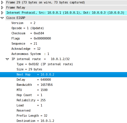
EIGRP update has non-zero next hop field
After the EIGRP adjacencies between R1 and R2/R3 are reestablished, the next-hop IP address of R2’s loopback interface in R3’s IP routing table is the WAN address of R2 (not R1):
R3#show ip route | begin Gateway
Gateway of last resort is not set

     10.0.0.0/8 is variably subnetted, 5 subnets, 2 masks
C       10.0.1.3/32 is directly connected, Loopback0
S       10.0.0.2/32 [1/0] via 10.0.0.1
D       10.0.1.2/32 [90/2809856] via 10.0.0.2, 00:09:38, Serial1/0
D       10.0.1.1/32 [90/2297856] via 10.0.0.1, 00:09:40, Serial1/0
C       10.0.0.0/24 is directly connected, Serial1/0
The modified next hop value is also displayed in the show ip eigrp topology printout, which indicates that the routing update has been received from R1 (10.0.0.1), but the next-hop field in the received update contains the IP address of R2 (10.0.0.2). The delay component of the vector metric and the hop count field have been increased (as compared to the EIGRP route toward R1’s loopback interface) when R1 has propagated the routing update between R2 and R3.
R3#show ip eigrp topology 10.0.1.2 255.255.255.255
IP-EIGRP (AS 1): Topology entry for 10.0.1.2/32
  State is Passive, Query origin flag is 1, 1 Successor(s), FD is 2809856
  Routing Descriptor Blocks:
  10.0.0.2 (Serial1/0), from 10.0.0.1, Send flag is 0x0
      Composite metric is (2809856/2297856), Route is Internal
      Vector metric:
        Minimum bandwidth is 1544 Kbit
        Total delay is 45000 microseconds
        Reliability is 255/255
        Load is 1/255
        Minimum MTU is 1500
        Hop count is 2
R3#show ip eigrp topology 10.0.1.1 255.255.255.255
IP-EIGRP (AS 1): Topology entry for 10.0.1.1/32
  State is Passive, Query origin flag is 1, 1 Successor(s), FD is 2297856
  Routing Descriptor Blocks:
  10.0.0.1 (Serial1/0), from 10.0.0.1, Send flag is 0x0
      Composite metric is (2297856/128256), Route is Internal
      Vector metric:
        Minimum bandwidth is 1544 Kbit
        Total delay is 25000 microseconds
        Reliability is 255/255
        Load is 1/255
        Minimum MTU is 1500
        Hop count is 1
Please note that it makes sense to use third-party next hops only when the routers can communicate with each other but cannot exchange routing updates. DMVPN Phase 2 networks are a typical example.
EIGRP Next Hop Processing in Route Redistribution Scenarios
The no ip next-hop-self eigrp interface configuration command affects internal and external EIGRP routes. This effect is easy to demonstrate in a sample three router network running two EIGRP processes (Figure 4).
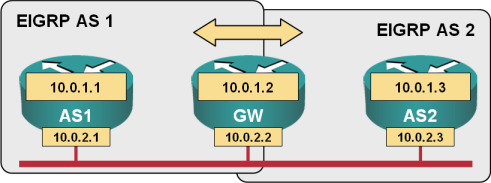
EIGRP redistribution test lab
The relevant configuration commands of the GW router are shown in the next printout:
interface FastEthernet0/0
 ip address 10.0.2.2 255.255.255.0
!
router eigrp 1
 redistribute eigrp 2
 network 0.0.0.0
 auto-summary
!
router eigrp 2
 redistribute eigrp 1
 network 0.0.0.0
 auto-summary
AS1 and AS2 belong to two different EIGRP processes; the no ip split-horizon eigrp interface configuration command is therefore not needed.
IP routing table on the GW router contains EIGRP routes from AS1 and AS2 with correct IP next hops.
GW#show ip route | begin Gateway
Gateway of last resort is not set

     10.0.0.0/8 is variably subnetted, 4 subnets, 2 masks
C       10.0.2.0/24 is directly connected, FastEthernet0/0
D       10.0.1.3/32 [90/156160] via 10.0.2.3, 00:01:30, FastEthernet0/0
C       10.0.1.2/32 is directly connected, Loopback0
D       10.0.1.1/32 [90/156160] via 10.0.2.1, 00:12:40, FastEthernet0/0
The GW router advertises the route to AS1’s loopback address as an external EIGRP route to AS2. With the default EIGRP interface parameters, the next-hop field in the EIGRP update packet is empty and all the traffic between AS2 and AS1 flows through the GW router:
AS2#show ip route | begin Gateway
Gateway of last resort is not set

     10.0.0.0/8 is variably subnetted, 4 subnets, 2 masks
C       10.0.2.0/24 is directly connected, FastEthernet0/0
C       10.0.1.3/32 is directly connected, Loopback0
D       10.0.1.2/32 [90/156160] via 10.0.2.2, 00:12:14, FastEthernet0/0
D EX    10.0.1.1/32 [170/158720] via 10.0.2.2, 00:12:11, FastEthernet0/0
To optimize the traffic flow between AS1 and AS2 you have to enable the EIGRP next hop calculations with the no ip next-hop-self eigrp command on the GW router. The next hop processing has to be enabled for both EIGRP processes:
interface FastEthernet0/0
 ip address 10.0.2.2 255.255.255.0
 no ip next-hop-self eigrp 1
 no ip next-hop-self eigrp 2
After the no ip next-hop-self eigrp command has been configured, the update packets sent from GW to AS2 contain non-zero values in the next-hop field:
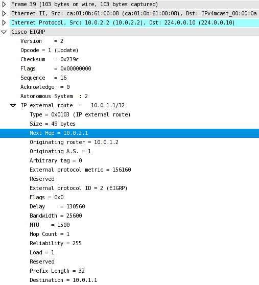
External EIGRP route with non-zero next-hop field
The next hop for the 10.0.1.1/32 prefix in the IP routing table of AS2 is modified accordingly; the traffic from AS2 to AS1 is sent directly and bypasses the GW router:
AS2#show ip route | begin Gateway
Gateway of last resort is not set

     10.0.0.0/8 is variably subnetted, 4 subnets, 2 masks
C       10.0.2.0/24 is directly connected, FastEthernet0/0
C       10.0.1.3/32 is directly connected, Loopback0
D       10.0.1.2/32 [90/156160] via 10.0.2.2, 00:12:14, FastEthernet0/0
D EX    10.0.1.1/32 [170/158720] via 10.0.2.1, 00:12:11, FastEthernet0/0
The non-zero value of the next-hop field is also reflected in the show ip eigrp topology printout:
AS2#show ip eigrp topology 10.0.1.1 255.255.255.255
IP-EIGRP (AS 2): Topology entry for 10.0.1.1/32
  State is Passive, Query origin flag is 1, 1 Successor(s), FD is 158720
  Routing Descriptor Blocks:
  10.0.2.1 (FastEthernet0/0), from 10.0.2.2, Send flag is 0x0
      Composite metric is (158720/156160), Route is External
      Vector metric:
        Minimum bandwidth is 100000 Kbit
        Total delay is 5200 microseconds
        Reliability is 255/255
        Load is 1/255
        Minimum MTU is 1500
        Hop count is 2
      External data:
        Originating router is 10.0.1.2
        AS number of route is 1
        External protocol is EIGRP, external metric is 156160
        Administrator tag is 0 (0x00000000)