MLAG Deep Dive: Layer-3 Forwarding
The layer-2 forwarding and flooding in an MLAG cluster are intricate but still reasonably easy to understand. Layer-3 gets more interesting; its quirks depend heavily on layer-2 implementation. While most MLAG implementations exhibit similar bridging behavior, expect interesting differences in routing behavior.
We’ll have to expand by-now familiar network topology to cover layer-3 edge cases. We’ll still work with two switches in an MLAG cluster, but we’ll have an external router attached to both of them. The hosts connected to the switches belong to two subnets (red and blue).
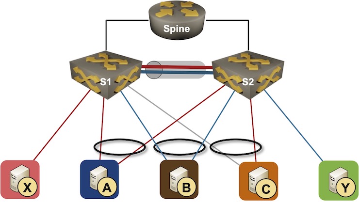
Layer-3 MLAG topology
Forwarding Requirements
Before going into the details, let’s figure out what we should expect in a well-designed MLAG cluster providing layer-3 forwarding:
- One of the primary reasons to deal with MLAG complexity is redundancy – the traffic should keep flowing even when one of the MLAG cluster members crashes. That’s easy to do within a layer-2 segment; to keep inter-subnet traffic flowing, the MLAG cluster members have to share the IP and MAC address of the first-hop gateway.
- We want active/active layer-3 forwarding across the MLAG cluster. For example, when A sends an IP packet to B, it might use the A-S1 or the A-S2 link. It would make no sense to send that packet over the S1-S2 peer link just to be routed by the other switch. The first-hop IP and MAC address must therefore be active on all MLAG cluster members.
- MLAG cluster members must deal with misdirected traffic. In most designs, S1 and S2 advertise whole subnets (red and blue) to the external router. While it doesn’t matter whether the external router sends traffic for A or B to S1 or S2, S1 and S2 have to deal with traffic for X or Y arriving at the wrong switch.
First-Hop IP and MAC Address
I’m positive the “shared first-hop IP- and MAC address” requirement immediately triggered the “first-hop redundancy protocols (FHRP)” knee-jerk reaction, but that doesn’t have to be the case. Arista’s Virtual ARP (VARP) or Cumulus Linux Virtual Router Redundancy (VRR) – statically configured shared IP- and MAC address – are more than good enough, and are pretty resilient against configuration mistakes.
Many other vendors insist on running HSRP or VRRP between MLAG cluster members, and Arista and Cumulus offer both options – what could be better than two ways of configuring the same thing.
Active/Active Forwarding
Many vendors took ancient FHRP implementations that supported a single active forwarder and made them part of their MLAG solutions. It took years before they realized it’s perfectly fine to have all switches listen to the same MAC address. After all, if the MAC table on the ingress switch forwards a layer-2 packet with the FHRP destination MAC address to the layer-3 forwarding table, that same packet is not flooded to any other host (or the peer link), and there’s no danger of traffic duplication.
Fast forward to 2022. Active/active forwarding is now a table-stakes MLAG feature, and there’s a good reason for that. Remember the “use outbound ACL to limit layer-2 flooding” trick? Here’s what happens when you try to use single forwarder with it:
- Let’s assume S1 is our dedicated forwarder, and S2 is just a layer-2 switch.
- Assume A wants to send a packet to B (which is in a different subnet) and happens to send the packet to the VRRP MAC address (owned by S1) over the A-S2 link.
- S2 forwards the packet (based on destination MAC address) to S1.
- S1 routes the packet, and tries to send it to B.
- The outbound ACL on the S1-B link drops the packet because S1 received it over the peer link.
You could solve that challenge with a more specific ACL (drop the packet if it came from the peer link and if the source MAC is not the router MAC1), or you could do the right thing and implement active/active forwarding.
Finally, since VXLAN and EVPN became all the rage, many switches support anycast gateway that extends the shared IP- and MAC addresses across the whole VLAN. Isn’t it ironic that it took so long for everyone to eventually converge toward the most straightforward solution that has been known for ages?
ARP Handling
I already mentioned misdirected traffic: an external source might send an IP packet to a switch that is not yet ready to forward it to a directly-connected host due to a missing ARP entry.
Many MLAG implementations use a control-plane protocol that synchronizes the ARP tables between MLAG cluster members to deal with that challenge; I still can’t figure out why they would have to do it. After all, the worst that can happen is another ARP request and a dropped packet (or few).
One might think (based on the active-active forwarding discussion) that you have to synchronize ARP entries due to misdirected ARP replies – S1 sends an ARP request to A, but A replies over the A-S2 link – but that doesn’t make sense.
ARP reply is a unicast layer-2 frame, and is forwarded to the control plane ASIC port once it reaches the target switch, so it’s not hitting the LAG member outbound ACL. Furthermore, should that be a challenge, we would have a 50% chance of getting ARP to work in the first place2, and probably a few unhappy unlucky customers.
It looks like most vendors decided that it doesn’t cost much to have ARP synchronization if they already implemented MAC synchronization, and just went with the flow.
Gateway Source MAC Address
MLAG implementations must deal with another glitch. Some devices (most notably storage devices, supposedly also some load balancers) build forwarding cache entries from the source IP- and MAC addresses of the incoming IP packets – a clear layering violation, probably also an RFC violation.
Let’s assume B is such a device. When A sends a packet to B over the A-S1 link, S1 routes the packet and forwards it to B with the S1 source MAC address. A sane IP host would ignore the source MAC address and send the return packet to the default gateway MAC address (after all, A is in a different subnet). B – an aggressively over-optimizing device – would build a forwarding entry from that packet saying “to send packets to A, use S1 MAC address”.
Now imagine that:
- B happens to send the packet to A with the destination MAC address of S1 over the B-S2 link
- S2 would forward (bridge) the packet to the S2-S1 peer link
- S1 would receive and route the packet and forward it toward A over the direct link.
- Based on the MLAG implementation, the packet might be dropped due to the outbound ACL on the S1-A LAG member link (see active/active forwarding section).
There are two ways to solve this conundrum:
- The academically correct way: use switch-specific MAC addresses for local traffic, and send all forwarded traffic with the shared source MAC address. Whatever the crazy hosts decide to do cannot break active-active forwarding.
- The usual kludge: make both switches process traffic sent to the shared MAC address and the local MAC addresses of both switches. This approach ensures no control-plane protocol (including ARP) will ever work out of the box, and requires tons of other kludges to make simple things like ARP work; the proof is left as an exercise for the reader.
Why would anyone implement such a crazy kludge? Wouldn’t it be easier to send forwarded packets and locally-originated packets with different source MAC addresses? After all, some network operating systems (like Cisco IOS) forever used different forwarding paths for local and forwarded traffic.
It looks like most data center switch vendors found it easier to push the locally-originated traffic to the switching ASIC and let it deal with the whole forwarding process (including outbound ACL). When using such an approach, the switch ASIC uses the same forwarding path for local traffic and traffic received on external ports, resulting in the same source MAC address after the layer-3 forwarding process rewrites the MAC header.
Thank You
There were many things that made little sense when I wrote the first draft of the blog post. A long chat with Dinesh Dutt cleared the MLAG fog, and all of a sudden everything made (some weird) sense. Dinesh, thanks a million for your time and the patience to help me figure it all out.
It goes without saying that all the errors left in the blog post are mine ;)
The next fun part starts when trying to run BFD on the MLAG. Scenario; There are 20 VMs running on servers connected to both switches, vSwitch with single LAG uplink on each server, static routes are created to anycast service IP on each VM, configured on switches to same /32 via 20 gateways, you want to use BFD to track next hop reach-ability...
Running a routing protocol with a neighbor connected via MLAG is also interesting. (peer routing)
question: One might think (based on the active-active forwarding discussion) that you have to synchronize ARP entries due to misdirected ARP replies – S1 sends an ARP request to A, but A replies over the A-S2 link – but that doesn’t make sense.
Ans:Thats because when S1 send ARP reply, forwarding(L3 decision) might have been still on A-S1 link, but mlag hash would have been resolved to use A-S2 link. So, now, at S2, because S2 knows that DMAC is of S1, it must send that that ARP reply packet over ISL Link to S1, otherwise, traffic will be dropped. hope that is clear.