… updated on Tuesday, February 15, 2022 15:42 UTC
Creating BGP Multipath Lab with netlab
I was editing the BGP Multipathing video in the Advanced Routing Protocols section of How Networks Really Work webinar, got to the diagram I used to explain the intricacies of IBGP multipathing and said to myself “that should be easy (and fun) to set up with netlab”.
Fifteen minutes later1 I had the lab up and running and could verify that BGP works exactly the way I explained it in the webinar.
Set Up the Environment
I decided to run my tests with container version of Arista EOS (cEOS) on a Ubuntu server. To replicate the labs you’ll have to:
- Set up a Linux server or virtual machine. If you don’t have a preferred distribution, use Ubuntu.
- Install Docker and containerlab (netlab install containerlab is the easiest way to do it on Ubuntu).
- Download and install Arista cEOS image.
Create Topology File
The mandatory first step when using netlab to create your virtual lab: create a YAML file describing the lab topology.
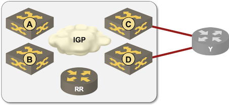
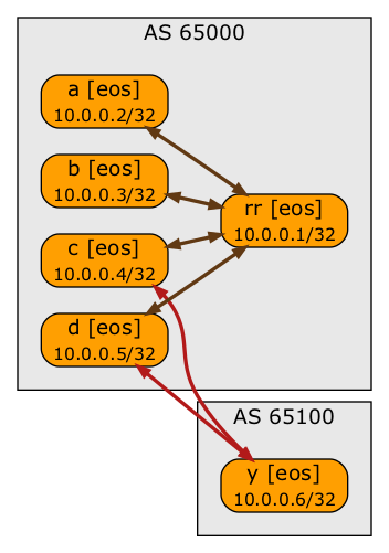
I used containerlab provider with eos devices, and placed most of my routers in AS 65000. External router (Y) would be in AS 65100. The network runs OSPF as the internal routing protocol, and a combination of IBGP and EBGP.
provider: clab
module: [ bgp, ospf ]
defaults.device: eos
bgp.as: 65000
There will be six nodes in the network – edge routers A through D, a route reflector, and an external router (Y). I had to set bgp.rr attribute on the route reflector, and I decided to use a static ID for that node so I’ll be able to quickly identify it in the printouts.
nodes:
  a:
  b:
  c:
  d:
  rr:
    bgp.rr: True
    id: 1
The external router is in a different autonomous system and needs to originate a BGP prefix:
  y:
    bgp.as: 65100
    bgp.originate: [ 10.42.42.0/24 ]
As an aside: here’s the corresponding data structure in pure YAML to illustrate what’s going on behind the scenes:
  y:
    bgp:
      as: 65100
      originate: [ 10.42.42.0/24 ]
Finally, we need the links connecting the routers. Here they are:
links: [ a-b, a-c, b-d, c-d, b-rr, d-rr, c-y, d-y ]
Validating the Topology
I used the netlab graphing capabilities together with graphviz to generate a diagram of the “physical” topology and BGP sessions. The diagrams were created with graphviz which has its own ideas how to place stuff. Their algorithms usually work well; for whatever reason my network diagrams always look messy.
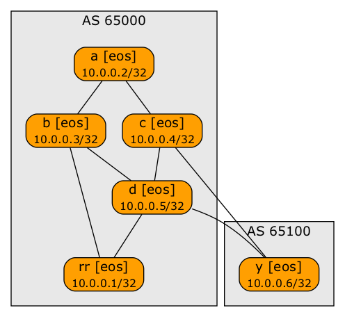
Lab topology created with netlab create -o graph && dot graph.dot -T png -o topo.png
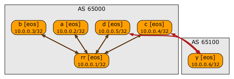
BGP sessions – created with netlab create -o graph:bgp && dot graph.dot -T png -o topo.png
The Smoke Test
Deploying a virtual lab is a one-liner: all it takes is netlab up baseline.yml (that’s how I named my topology file) and you get a configured lab a minute or two later2.
I had to wait a few more minutes for BGP to start and announce the configured prefixes. After that, I used netlab connect a to connect to router A, and executed a few commands.
Let’s look at the loopback addresses first (so you’ll understand the show printouts):
a#show hosts

Default domain is not configured
Name/address lookup uses domain service
Name servers are:
IP Address VRF Priority
---------- --- --------

Static Mappings:
Hostname IP   Addresses
-------- ---- ---------
b        IPV4 10.0.0.3
              10.1.0.9
              10.1.0.2
              10.1.0.17
c        IPV4 10.1.0.13
              10.1.0.25
              10.1.0.6
              10.0.0.4
d        IPV4 10.0.0.5
              10.1.0.14
              10.1.0.21
              10.1.0.29
              10.1.0.10
rr       IPV4 10.1.0.22
              10.1.0.18
              10.0.0.1
y        IPV4 10.1.0.26
              10.0.0.6
              10.1.0.30
Now for the real test: the route toward 10.42.42.0/24.
a#show ip bgp 10.42.42.0
BGP routing table information for VRF default
Router identifier 10.0.0.2, local AS number 65000
BGP routing table entry for 10.42.42.0/24
 Paths: 1 available
  65100
    10.0.0.5 from 10.0.0.1 (10.0.0.1)
      Origin INCOMPLETE, metric 0, localpref 100, IGP metric 30, weight 0, tag 0
      Received 00:00:57 ago, valid, internal, best
      Originator: 10.0.0.5, Cluster list: 10.0.0.1
      Rx SAFI: Unicast
As expected, the route is coming from the route reflector (10.0.0.1) and the next hop is 10.0.0.5 (D), even though it would be better for A to use C as the next hop.
Revenge of the IGP
How about a simple brain-teaser? This is the traceroute printout from A to Y (taken from the IOS version of the lab, see below):
a#trace y source loop 0 probe 5
Type escape sequence to abort.
Tracing the route to y (10.0.0.6)
VRF info: (vrf in name/id, vrf out name/id)
  1 b (10.1.0.2) 2 msec
    c (10.1.0.6) 2 msec
    b (10.1.0.2) 3 msec
    c (10.1.0.6) 3 msec
    b (10.1.0.2) 3 msec
  2 y (10.1.0.26) 4 msec
    d (10.1.0.10) 4 msec *  5 msec
    y (10.1.0.26) 3 msec
As you can see, sometimes the probes reach Y in two hops, and sometimes the second hop happens to be D. What’s going on? Write a comment!
Testing Other Platforms
Another beauty of netlab is the ease of changing network devices or virtualization providers. All I had to do to replace Arista EOS with Cisco IOSv was two extra parameters in the netlab up command:
netlab up baseline.yml --device iosv --provider libvirt
A few minutes later, I had an identically configured lab, this time running Cisco IOS. I could have repeated the same tests on over a dozen devices supported by netlab (if only I had all the necessary Vagrant boxes installed)
Coming up next: fixing suboptimal BGP routing with additional paths functionality.
Off-Topic: Nicer-Looking Graphs
Jeroen van Bemmel suggested using graphviz rankdir parameter to generate better-looking graphs. As you can set individual graph options with CLI parameters, I didn’t have to change the .dot files generated with netlab create. All I had to do was to add an extra parameter to the dot command:
dot -Grankdir=LR -T png -o graph.png graph.dot
Here are the results:
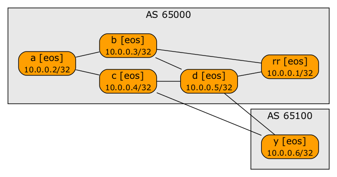
Lab topology created with rankdir=LR
BGP sessions diagram created with rankdir=LR
Change History
- 2021-11-10
- Added graphviz graphs created with
rankdir=LR - 2021-11-09
- Fixed the list of links based on a comment from an anonymous contributor
"A" has two routes (ECMP probably due to equal IGP cost) to "D" next-hop (from IBGP advertisement from "RR") . As "C" is peering with "Y" directly via EBGP, it's prefering the path via EBGP. Hence if a packet from "A" is hitting "C", it's going directly to "Y". This would be a use case for BGP ORR, isn't it? :D
You got it... but you REALLY SHOULD HAVE started your comment with "spoiler alert" 😆
And yes, this is where ORR would save the day, but so would a more symmetrical network design.
You could warn your readers of your blog post (assuming they read it top down) to think first and then look for the answer in the comments ;)
Yes, "RR" should have been placed more symmetrical (from a IGP cost perspective) within the network. Or implement multiple RRs (in a symmetrical way) and having BGP Multipath configured on "A". With that you would also benefit from redundancy.
I read that you'll bring BGP ADD-PATH (RFC 7911) into the mix. So you could have something along BGP PIC Edge with subsecond convergence :D Looking forward to...
Found a typo in your "links" list: "c-x, d-x" should be "c-y, d-y"
Thank you. Fixed.
You are a never-ending source of unexpected wisdom. Thanks a million, it does look better when using
Will add that to the blog post.
RRs are commonly becoming a host (vs router) based technology (and they should) and are per definition placed suboptimal wrt its clients, and this is the main use of ORR
"RRs are commonly becoming a host (vs router) based technology (and they should)" << that's a technologist perspective that quickly leads to circular dependencies
https://blog.ipspace.net/2021/10/circular-dependencies-considered-harmful.html
I'm not saying you can't get it right, but I'm positive a lot of people will implement this concept in the worst possible way.
And yes, once you believe in pulling RR far away from the forwarding path, ORR becomes increasingly useful.