Arista EOS Virtual ARP (VARP) Behind the Scenes
In the Optimal L3 Forwarding with VARP and Active/Active VRRP blog post I made a remark along the lines of “Things might get nasty [in Arista EOS Virtual ARP world] if you have configuration mismatches”, resulting in a lengthy and amazingly insightful email exchange with Lincoln Dale during which we ventured deeper and deeper down the Virtual ARP (VARP) rabbit hole. Here’s what I learned during out trip:
Optimal VARP Deployment
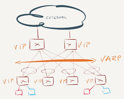
You should deploy identical VARP configuration (VARP IP and MAC address) on all ToR (leaf) and core (spine) switches. This design not only ensures optimal L3 forwarding between any two ToR endpoints, but also optimal inbound (external client to server) traffic forwarding.
VARP Design
All other designs (or configuration mismatches) result in suboptimal forwarding, but don’t cause packet forwarding loops or duplicate/dropped packets due to another VARP feature: periodic gratuitous ARP packets sent from all VARP-enabled switches.
A Day in VARP’s Life
VARP is enabled immediately after you configure virtual router IP and MAC address on an Arista EOS switch – it requires no protocol between VARP-enabled nodes and has no concept of primary/backup forwarders. The moment you configure VARP, the switch starts replying to ARP requests for the virtual router IP address with the virtual router MAC address (the ARP reply is sent from the physical MAC address of the switches).
End hosts use VARP virtual MAC address to send packets to the first-hop router. The first VARP-enabled L3 switch in the forwarding path grabs the packet (based on the router MAC address entries in its TCAM) and performs L3 lookup.
An IP packet forwarded by a VARP-enabled L3 switch is sent from the physical MAC address of the L3 switch, not from the VARP virtual MAC address. The virtual MAC address is "silent" (no traffic is sent from that MAC address), which caused my initial concern – unicast packets sent to the virtual MAC address might get flooded by L2 switches in the path, resulting in multiple copies of the same packet being forwarded to another VLAN.
Arista solved the unicast flooding problem with periodic gratuitous ARP replies sourced from the shared VARP MAC address. Every VARP-enabled switch sends the GARP broadcasts and you can configure the advertisement interval (it should be several times smaller than MAC aging timer); the default value is 30 seconds.
A VARP-enabled Arista switch receiving gratuitous ARP reply will ignore it (after all, it knows what’s going on) and will not try to protect its own IP address1. Likewise, an Arista EOS switch ignores the fact that broadcasts from the same MAC address come from numerous ports (this behavior might trigger flapping MAC addresses warnings in traditional bridging implementations).
End result: every switch in the network either receives traffic sent to the VARP MAC address (if it has VARP configured) or forwards the traffic toward the last switch that sent gratuitous ARP broadcast from the VARP MAC address.
Impact of VARP Configuration Errors
Now let’s see how a L2+L3 leaf-and-spine fabric (with two core switches in a MLAG group) reacts to VARP configuration errors by walking through several bad designs and VARP configuration errors, starting with the easiest one.
These scenarios assume that the core switches in the leaf-and-spine fabric connect the fabric with the outside world.
VARP is enabled on spine (core) switches but not on leaf switches
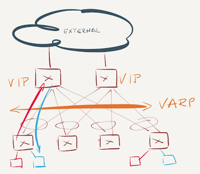
VARP is enabled on spine switches
The core switches reply to ARP requests for VARP virtual IP address and receive traffic for VARP virtual MAC address. Inter-subnet traffic flows through the core switches. Not optimal, but not too bad either (depending on the amount of inter-subnet east-west traffic).
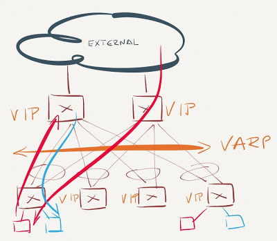
VARP is enabled just on the leaf switches

VARP is enabled on the leaf switches
Inter-subnet east-west traffic is forwarded optimally, as is traffic from servers toward external clients. Traffic from external clients toward the servers takes one of two paths:
- If the core switches participate in L3 forwarding for the VARP-enabled VLAN (they have an IP address in VARP-enabled VLAN, but don’t share the VARP address), they perform the L3 forwarding between external world and destination (VARP-enabled) subnet;
- If the core switches don’t have an IP address in the VARP-enabled VLAN, they have to learn about the VARP-enabled IP subnet from the ToR (leaf) switches through a routing protocol. With all ToR switches advertising the VARP-enabled IP subnet, the core switches have N equal-cost paths toward that subnet (with N being equal to the number of the ToR switches), and the probability that a core switch forwards the packet to a wrong ToR switch equals (N-1)/N. All misdirected packets have to be L3-forwarded by the target ToR switch and sent back to the final ToR switch through the leaf-to-spine uplink.
Summary: Make sure VARP is always configured on spine switches.
VARP is enabled on the spine switches and some leaf switches
VARP is not enabled on some leaf switches
Traffic entering the network from servers connected to non-VARP-enabled ToR switches will be sent toward the closes VARP virtual MAC address – the spine switch. The spine switch will perform L3 forwarding, potentially sending the packet back to the same leaf switch. While some of the east-west traffic might take suboptimal paths, the traffic to and from the outside world will always flow optimally.
VARP is enabled just on a subset of leaf switches
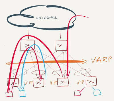
VARP is enable just on a subset of leaf switches
This is the worst possible scenario. Traffic sent from the servers in VARP-enabled subnet might have to traverse the network core to be forwarded on another ToR switch. Even worse, all inter-subnet traffic entering non-VARP ToR switches will be sent to the same VARP-enabled ToR switch - the one that last sent gratuitous ARP broadcast.
Assuming the core switches don't participate in L3 forwarding for the VARP-enabled subnet, they'll send the traffic to one of the VARP-enabled ToR switches (see VARP is enabled just on the leaf switches scenario), yet again resulting in suboptimal traffic flow.
Summary
VARP is a simple and extremely effective mechanism to achieve optimal L3 forwarding across a data center fabric, assuming you consistently deploy it on all switches in the fabric. At the very minimum, you should deploy VARP on ToR switches participating in the VARP-enabled VLAN and on all core switches.
VARP does rely on somewhat non-standard behavior (same MAC address being advertised by numerous switches), so make sure you test it first before a deployment in a mixed-vendor environment.
Revision History
- 2023-02-01
- Minor rewordings/cleanups
-
If you don’t know what I’m talking about, try configuring the same IP address on two or more switches. ↩︎
Careful planning would be needed to ensure that the first/last 10-20 addresses of any subnet are reserved for the 'real' ip addresses used by the ToR switches.
I wonder if this could be modified somehow to let you simply do
ip virtual-router address 10.10.20.1/24
and not have to individually address each ToR switch.
Obviously the switch would lose the ability to source packets from that interface, but I'm not sure what else would break.
Oh, and do I have to mention that this problem will go away with IPv6 ;)
Unless VARP only works in the context of MC-LAG. In this case, when SW1 detects the downlink, it generates GARP requests that will be flooded to SW2 then back to SW3 which will now use SW2's port for the virtual MAC.