Building a Small Data Center Fabric with Four Switches
One of my subscribers has to build a small data center fabric that’s just a tad too big for two switch design.
For my datacenter I would need two 48 ports 10GBASE-T switches and two 48 port 10/25G fibber switches. So I was watching the Small Fabrics and Lower-Speed Interfaces part of Physical Fabric Design to make up my mind. There you talk about the possibility to do a leaf and spine with 4 switches and connect servers to the spine.
A picture is worth a thousand words, so here’s the diagram of what I had in mind:
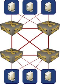
Four Switch Fabric
Although a four-switch fabric does look like a leaf-and-spine fabric if you squint hard enough it’s not. It’s just four switches with a full mesh of links between them, and although full mesh does happen to be the worst possible fabric architecture it’s good enough for this particular use case assuming the traffic requirements aren’t too high.
Talking about traffic requirements – my subscriber also wondered if it’s worth optimizing server connectivity:
Wouldn’t it be better to connect all servers to all switches (with four uplinks) in such a way that we reduce the distance between servers?
I think that’s over-complicating the design. Most small fabrics won’t have traffic- or latency requirements that would justify that kind of connectivity. Also, assuming you really needed four switches in the first place, you’d run out of switch ports.
For more details, watch the Leaf-and-Spine Fabric Architectures webinar.
The traffic would flow over the optimal paths if the two switch pairs were connected via MLAG, and all servers were connected to one switch pair via MLAG. But this would be a boring legacy setup that may allow for interesting, but rare, failure scenarios. Additionally, VMware still prefers MAC based redundancy and load sharing instead of using LACP based LAGs. ;-)
In a more fashionable layer 3 setup with VXLAN overlay (or an SPB-M based fabric à la Extreme), the link between switches of the same pair could be omitted unless an MLAG construct requires it (some vendors support virtual MLAG peer links), or it could be configured with a higher metric value such that it is not used for IP (resp. MAC-in-MAC) forwarding unless the two links to the other switch pair both fail. This again would result in optimal forwarding.
If later there is a need to add more switches, a spine layer could be added "in the middle."
Thus with care for the details the physical full mesh is either not needed or not detrimental, depending on circumstances (which include the selected switch models and network operating systems, among other things).
Simple routed fabric (with EVPN if L2/overlay is needed) would do just fine
IMHO the question is what to do with the worrisome extra links between switches of a pair that turns the topology into a full mesh instead of just collapsing the spines into the leafs.
I think good answers are to remove them, or to not use them for IP forwarding and/or underlay transport, unless required (because of failed links), but be able to make use of those links if necessary (i.e., do not omit them from IP and/or underlay forwarding).
This would remove the doubts about traffic requirements noted in the blog post.
(YMMV depending on make and model of your switches and NOS.)
I don't understand why you find those links worrisome. There is no central switching fabric in this design, and the full mesh is probably the best you can do assuming you have no prior information on traffic flows. The proof is left as an exercise for the reader 😜
Also, it's a small fabric, so it's worth keeping complexity to a minimum, thus no MLAG.
According to the diagram, servers are connected to one of two switch pairs. This is supported by using two different connection types, 10G copper vs. 10G/25G fiber, which is seldomly combined on a single server.
Server to server (resp. VM to VM) ingress traffic of a given switch falls into three cases (without any link or device failures in the network):
Case 1 is trivially optimal regardless of inter switch links.
With a full mesh and active/passive VM or server redundancy ("no MLAG"), both case 2 (intra switch pair) and case 3 (inter switch pair) traffic uses a single egress link.
Without intra switch pair links (or high IP/underlay metric for those links) and active/passive VM or server redundancy ("no MLAG"), case 2 would use two egress links, while case 3 would still use a single egress link.
Without intra switch pair links (or high IP/underlay metric for those links) and active/active VM or server redundancy (e.g., MLAG, EVPN multi-homing, or IP with routing protocol on the servers), case 2 is eliminated and case 3 uses two egress links.
Adding two more switches as a "spine" and removing the intra switch pair links enables use of two egress links for cases 2 & 3 of the "no MLAG" variant, but adds both capex and opex.
Implicit requirements (e.g., servers don't use LAGs, MLAG is too complicated) can result in unnecessarily sub-optimal design decisions. The assumption that every host (VM or server) is effectively single attached (active/passive redundancy) leads to the conclusion that a full mesh is optimal for the "two switch pairs" design.
If these details were made explicit (e.g., "we use virtualization solution X and switch family Y, thus server LAGs and MLAG on switches are complicated and brittle"), the full mesh were a good solution, because optimizing just case 2, but not case 3, would be an unneeded complication without additional knowledge about traffic flows.
Both not blocking any inter switch links and using more than one egress link is another implicit requirement that leads to using a suitable technology. Both can be fulfilled for layer 2 and layer 3 traffic using different widely available solutions (details depend on the used switches).
This shows that even a small fabric warrants a closer look.
(LACP based LAGs for server redundancy to an MLAG pair can be both simple and reliable, depending on vendor choices, of course.)
@Erik, I am probably not knowing enough about the nuances here and missing something deep, but I don't understand several points in your comment, which is very interesting and thought-provoking.
Let's say we use a simple routed fabric here with standard ECMP routing protocol, and very high metric intra-pair link. You said:
"Without intra switch pair links (or high IP/underlay metric for those links) and active/passive VM or server redundancy ("no MLAG"), case 2 would use two egress links, while case 3 would still use a single egress link."
How? With ECMP, traffic reaching the first switch from a server, will be load-balanced among the 2 uplinks, so case 3 would use both egress as well.
"Without intra switch pair links (or high IP/underlay metric for those links) and active/active VM or server redundancy (e.g., MLAG, EVPN multi-homing, or IP with routing protocol on the servers), case 2 is eliminated and case 3 uses two egress links."
By eliminated, you probably mean case 2 is now generalized into case 1? In this case, case 3 can use at most 4 uplinks via the 2 switches it connects directly to, not 2.
So adding 2 more spine switches doesn't improve anything, unless I miss something major.
"Implicit requirements (e.g., servers don't use LAGs, MLAG is too complicated) can result in unnecessarily sub-optimal design decisions. The assumption that every host (VM or server) is effectively single attached (active/passive redundancy) leads to the conclusion that a full mesh is optimal for the "two switch pairs" design."
I don't think Ivan made this assumption, since he's a routing guy at heart. In this case, since the fabric is small, I can't see much leeway/need for optimization here, regardless of traffic profile. A good design heuristic: group the servers/devices that perform similar functions, e.g. storage, into one rack, to avoid "strange attractors" infesting uplinks and drawing traffic toward them, causing congestion -- yes, congestion happens way below the 100% utilization threshold, for the Internet it starts happening at 35-40%. Apart from that, a rack of this size needs little optimization. We should avoid overoptimization, as it's a inherently dumb process and leads to unnecessary complexity.
Also, MLAG and SPB are not simple. The commands to configure them are simple, the implementations are complex and potentially buggy. The SD-WAN snafu is one such example.
Perhaps Ivan should make a blog post dissecting the cases you've mentioned in detail, as they potentially contain tidbits that one overlooks at first glance.