Creating Dynamic Network Diagrams with Graphviz
Articles » Yet Another Network Automation Journey » Creating Dynamic Network Diagrams
While it is not equally relevant in all environments, it can be handy to create network diagrams dynamically (or on request), for instance, when the network includes mobile devices that are routinely moved around, shut down, or reconnected. It is possible to include interface information in the network diagrams, but I found those diagrams become too cluttered, and preferred the simple version without interface information.

Overall Network Diagram
The above diagram is auto-generated daily with Graphviz. While it might not be particularly useful, it showcases some of the nice possibilities of Graphviz. Each color corresponds to a different Ansible group - a number determining the color of the devices in the group based on the Graphviz color scheme attribute is defined for each group of devices in Ansible inventory. The options to control node placements for diagrams with more than 3 levels are limited.
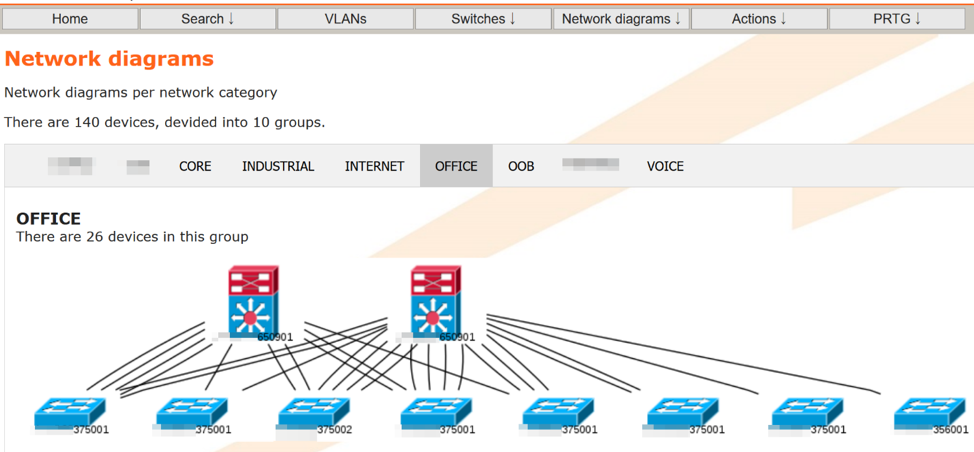
While the network diagram including all devices is more of a talking piece than actually useful, the diagrams for the different parts of the network are an excellent planning or troubleshooting tool. In these diagrams, I have used a Graphviz option to replace a simple rectangle with a device icon image.

Office Network Diagram
This article is an account of how to get started with network automation, and some common use cases. You can reach Anne via LinkedIn.
