Multi-chassis Link Aggregation: Stacking on Steroids
In the Multi-chassis Link Aggregation (MLAG) Basics post I’ve described how you can use (usually vendor-proprietary) technologies to bundle links connected to two upstream switches into a single logical channel, bypassing the Spanning Tree Protocol (STP) port blocking. While every vendor takes a different approach to MLAG, there are only a few architectures that you’ll see. Let’s start with the most obvious one: stacking on steroids.
The Basics
Low-end devices have provided multi-chassis link aggregation for a long time and nobody realized it’s a big deal. After all, a stackable switch is just a stackable switch; in opinion of many networking engineers that’s not necessarily a sin, but neither is it something to be very proud about.
When the vendors decided to introduce the same mentality to the core Data Center switches, they couldn’t say “well, we just made our core switches stackable”; their marketing department had to invent a fancy name for the technology, be it Virtual Switching System (Cisco) or Intelligent Resilient Framework (HP).
Regardless of the branding efforts, the architecture of VSS/IRF solution still looks and feels like a stackable switch: you take X independent boxes (X = 2 in VSS case) and turn all but one brain (= control plane) off. Distributed switching subsystems add some spice (= complexity) to the mix. For example, in a VSS system, the SUP blade in the secondary chassis still controls its switching fabrics.
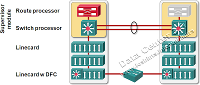
VSS Architecture Overview
With all the control planes but one gone into self-induced coma (vendors prefer the term standby), it’s easy to implement link aggregation. After all, the primary control plane receives all control packets (including LACP and STP messages) and directly or indirectly (through standby control planes) controls the switching fabrics in the whole system.
The traffic flow across the whole stacked system is usually optimal. Consider, for example, the following diagram:
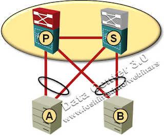
Typical VSS deployment
When server A sends a packet to server B through the Primary switch, the Primary switch automatically updates its own MAC address table and the MAC address table on the Standby switch (both entries for MAC address A point to local links in the port channel with server A). When server B sends a subsequent packet to server A it uses the optimal path and does not traverse the inter-switch link.
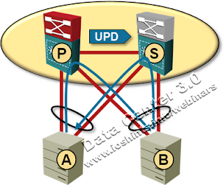
MAC table synchronization in VSS cluster
Schizophrenia
The worst scenario in any stackable solution is a split-brain failure – the link between the primary switch and standby switches is lost while the access links remain operational.
In a pure layer-2 solution, split-brain failure is not necessarily a disaster. The standby switch discovers the primary switch is gone, becomes independent (causing, among other things, STP topology change) and tries to renegotiate port channels (Cisco’s name for link aggregation groups – LAG) with a different switch ID, which causes a port channel failure. Depending on how the connected switches implement port channels, they could split the port channel in two independent links (and STP would block one of them) or shut down half of the links in the port channel.
Layer-3 split brain event is a cataclysm. All of a sudden you have two routers with the same set of IP addresses and same router IDs in your network. Try to imagine what that does to your ARP caches and routing protocol and how long the post-traumatic effects will linger after you manage to shut down one of the switches (in case of OSPF, up to one hour).
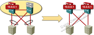
Layer-3 split brain is a disaster
Read the Smallprint
If a vendor tells you virtual device partitioning is not a problem, run away… or ask them how they handle layer-3 problems, grab some popcorn, lean back, and enjoy the show.
The methods vendors use to deal with detecting and recovering from device partitioning tells you a lot about their commitment to the stability of your network. Don’t be dazzled by the flamboyant approaches like “this can never happen”; personally I prefer to see someone who thought seriously about the problem and tried hard to detect it and recover from it (even though we agree it should never happen).
Consider, for example, design recommendations and dual-active detection technologies used by Cisco’s VSS (a stack of Catalyst 6500s):
- You should use multiple physical links bundled into a channel for the Virtual-Switch Link (VSL);
- Apart from VSL, there should be an independent keepalive link between the switches.
- BFD is run on the keepalive link to distinguish between switch failure and VSL failure;
- If you have Cisco’s switches connected to the VSS complex, you can run Enhanced Port Aggregation Protocol (EPagP) across some port channels to allow the VSS switches to communicate across access switches.
As for what happens when the dual-active condition is detected, Cisco is yet again quite honest: the primary switch is immediately restarted (assuming the standby switch has already transitioned into an active role).
Avaya/Nortel have greats solutions for dual (or more) chassis aggregation. Their switches are stackable on all series, most of them with more than 180Gbps between stack units via stack-cross cables.
In dual chassi redundancy, they have Multilink Trunking technologies (MLT is like Etherchannel). MLT have various flavors, like:
SLT - Single Link Trunking - triangle topology with dual Core switches and one third, dual homed. The connection is single to each core.
SMLT - Split Multilink Trunking - Same as SLT, but now you can aggregate links between your third device (a distribution L2 switch) and the cores. Up to 8 x 10Gbps link aggregation per connection.
RSMLT - Routed Split Multilink Trunking Same as SMLT, but now with L3 (OSPF added).
All this more features like SLPP - Simple Loop Prevention Protocol - provides active protection against Layer 2 network loops on a per-VLAN basis. SLPP uses a lightweight hello packet mechanism to detect network loops. SLPP packets are sent using Layer 2 multicast and a switch will only look at its own SLPP packets or at its peer SLPP packets. It will ignore SLPP packets from other parts of the network. Sending hello packets on a per VLAN basis allows SLPP to detect VLAN based network loops for un-tagged as well as tagged IEEE 802.1Q VLAN link configurations.
Well, that is it.
Perhaps things have imporved since then.
for us it was even more painful: we have migrated from SMLT which really falls apart when one of the switches fails to MSTP (due to new Enterasys switches, which are very primitive in terms for features) only to find that Nortel was so impressed with SMLT, that some bugs were left unpatched in MSTP...
Kireeti Kompella of Juniper will present a tutorial on MPLS in the Cloud Computing and Data Centers in MPLS 2010 conference. Should be very interesting talk but unfortunately wont have access to it.
A major difference between VSS and the nt/avaya ERS products is that with ERS and SMLT, each chassis has an active CPU with a distributed control plane over the set of 2-4 chassis in a cluster. Of course, a redundant CPU is there as well in each chassis and support hot standby IIRC. In VSS (at least initially when I looked at it) you could only have 1 Sup in each chassis (ISSU support for example) and a wide variety of things render your cat6500 non-VSS capable (non-E chassis, WAN and most app/services modules, anything older than DFC3C, etc.) hopefully nobody will buy a cat6500 VSS and instead will go to Nexus.
It works very much like VRRP.