Create Network Models with CML’s AutoNetKit
Last week I described how Cisco Modeling Lab (CML, the product formerly known as VIRL) works behind its fantastic UI, and promised more information about the UI once I get access to a preview version of CML, which I got a few days ago. Here are the results of the first brief stroll down the virtual lane.
Brief recap
CML has two major components: a network modeling engine (AutoNetKit) and a simulation engine.
After creating the network model (including initial configurations) in the modeling engine, you can start the simulation, either locally or somewhere else. The communication between the UI and back-end simulation engine runs over HTTP, allowing you to build all sorts of interesting simulation-as-a-service environments.
Create the topology
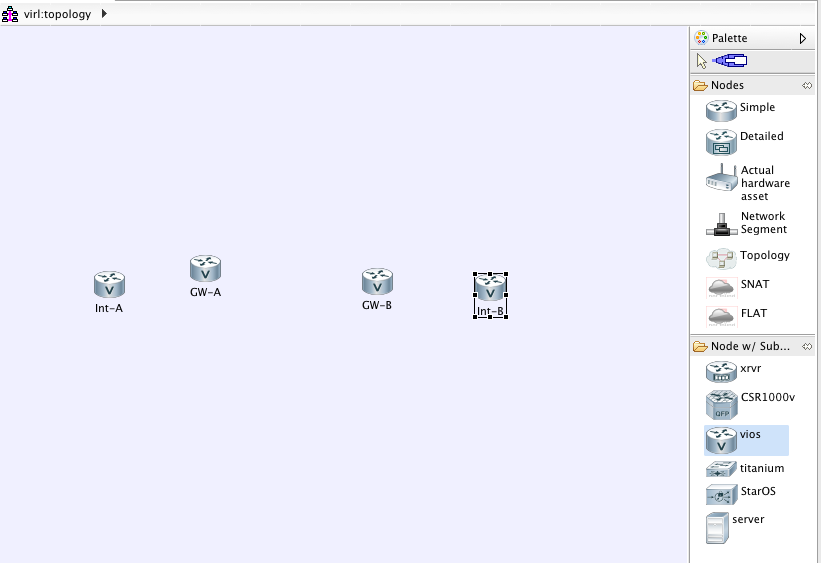
After a brief struggle with the initial setup (totally my fault, I should have read the documentation first), I got to the main topology window, which allows you to add new devices to the simulated network.
Adding nodes is exceedingly simple: click on the node type, click on the topology canvas, and you have a new node.
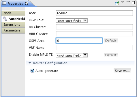
You can set a node’s properties immediately after adding the node. As you can see in the following screenshot, AutoNetKit helps you build BGP and OSPF (or IS-IS or EIGRP) topology, and layer-3 VPNs.
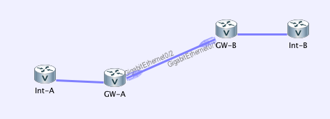
Next step: connect the devices. As simple as clicking on them. Device interfaces are created automatically (and they all have to be Gigabit Ethernet interfaces – no serial links or ATM … but then it’s pretty easy to simulate serial links with PPPoE).
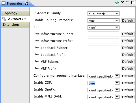
Last step (or maybe the first one if you read the documentation ;) – set global AutoNetKit properties. You can decide to have IPv4, IPv6 or dual-stack network, set address ranges, choose the default routing protocol, and a few other bits and pieces.
Create the initial configurations
A single click on the menu creates initial configurations of all routers in the topology. Here’s the configuration of my GW-A router (edge BGP router in an autonomous system):
hostname GW-A
!
ip cef
ipv6 unicast-routing
ipv6 cef
!
service timestamps debug datetime msec
service timestamps log datetime msec
no service password-encryption
no service config
enable password cisco
ip classless
ip subnet-zero
no ip domain lookup
line vty 0 4
 exec-timeout 720 0
 password cisco
 login
line con 0
 password cisco
!
!
cdp run
!
!
interface Loopback0
  description Loopback
  ip address 192.168.0.1 255.255.255.255
  ipv6 address ::a:1:0:0:1/128
  ipv6 ospf cost 1
  ipv6 ospf 1 area 0
!
interface GigabitEthernet0/1
  description to Int-A
  ip address 10.0.0.1 255.255.0.0
  ipv6 address ::b:1:1:0:5/126
  cdp enable
  ip ospf cost 1
  ipv6 ospf cost 1
  ipv6 ospf 1 area 0
  duplex auto
  speed auto
  no shutdown
!
interface GigabitEthernet0/2
  description to GW-B
  ip address 10.1.0.1 255.255.128.0
  ipv6 address ::b:2:1:0:5/126
  cdp enable
  duplex auto
  speed auto
  no shutdown
!
!
router ospf 1
# Loopback
  network 192.168.0.1 0.0.0.0 area 0
  log-adjacency-changes
  passive-interface Loopback0
  network 10.0.0.0 0.0.255.255 area 0
router ospfv3 1
  router-id 192.168.0.1
  !
  address-family ipv6 unicast
  exit-address-family
!
!
router bgp 65001
  bgp router-id 192.168.0.1
  no synchronization
  network 192.168.0.1 mask 255.255.255.255
! ibgp
  ! ibgp peers
  !
  neighbor 192.168.0.2 remote-as 65001
  neighbor 192.168.0.2 description iBGP peer Int-A
  neighbor 192.168.0.2 update-source Loopback0
  neighbor 192.168.0.2 next-hop-self
  !
  neighbor ::a:1:0:0:2 remote-as 65001
  neighbor ::a:1:0:0:2 description iBGP peer Int-A
  neighbor ::a:1:0:0:2 update-source Loopback0
  neighbor ::a:1:0:0:2 next-hop-self
!
! ebgp
  !
  neighbor 10.1.0.2 remote-as 65002
  neighbor 10.1.0.2 description eBGP to GW-B
  neighbor 10.1.0.2 send-community
  neighbor 10.1.0.2 next-hop-self
  !
  neighbor ::b:2:1:0:6 remote-as 65002
  neighbor ::b:2:1:0:6 description eBGP to GW-B
  neighbor ::b:2:1:0:6 send-community
  neighbor ::b:2:1:0:6 next-hop-self
!
!
end
AutoNetKit did a great job – all the BGP sessions are configured correctly (IBGP between loopbacks, EBGP between directly-connected addresses) and OSPF runs only within an autonomous system.
Changing the (virtual) hardware
Want to replace IOS devices with IOS XR devices? No problem, change the node subtype in the network topology from vIOS to xrvr, click on the build configurations icon, and you have initial configurations in IOS XR format.
Launching the network model
You could (if you wish) modify the initial configuration files, but it’s probably much simpler to do that in a running network (and then extract the configuration files before shutting down the network model).
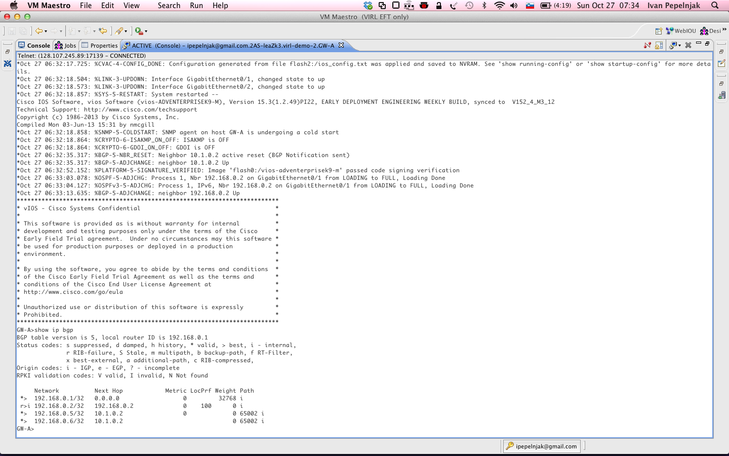
A single click on the menu launches all device instances. CML console window opens and you can watch the lab being built:
Once all the nodes become active, all you have to do is click on a node and telnet to its console port.
Summary
I like what I’ve seen so far:
- Creating network topology in GUI is nice;
- Deploying the topology on a configurable target environment is great;
- Having automatically generated initial configurations with IP addresses and reasonably configured routing protocols is awesome.
Whenever I wanted to do a quick test of a new IOS feature in the past, I spent more time creating the initial router configurations (or browsing through previously created topologies and configurations, trying to figure out which ones would closely match my current requirements) than doing the actual tests (I even wrote a Perl script to create the configurations).
The ability to create a topology on the fly and get a running network in a few minutes is priceless.
Not sure if this is still what Cisco's plan is. The version I saw was running on Vmware Fusion on a Mac laptop. The front end application was pointed at a back end server where all of the VMs were running. Just like in GNS3 where you can specify a remote hypervisor (running on Amazon, etc).
Another notable feature is that you are not just limited to running the Cisco IOS VMs. Since it leverages KVM, you can also virtualize host operating systems, or any other "virtualizable" thing. This means that one can integrate all of these other VMs on the topology (just like one can use a host operating system vm with GNS3).
It also provides means of connecting the topology to the physical network. For example, a company using the appliance could feed the BGP table to the virtual network via a BGP session between a virtual XR instance and a physical BGP router on the network.
...The possibilities are endless =)
You will have access to Titanium (Nexus OS), but this is not like the l2 switches that you have in IOU.