… updated on Friday, December 4, 2020 14:02 UTC
MPLS TE Autoroute Fundamentals
An MPLS Traffic Engineering (MPLS TE) tunnel is a unidirectional Label Switched Path (LSP) established between the tunnel head-end Label Switch Router (LSR) and tail-end LSR. Once the tunnel is established and operational, it’s ready to forward IPv4 data traffic. However, no traffic will enter the tunnel unless the IPv4 routing tables and CEF tables are modified. You can push the traffic into an MPLS TE tunnel with a static route or with policy-based routing (PBR) or modify the behavior of the link-state algorithm used to implement MPLS TE in your network.
The autoroute functionality configured with the tunnel mpls autoroute announce interface configuration command automatically inserts the MPLS TE tunnel in the SPF tree and ensures the tunnel is used to transport all the traffic from the head-end LSR to all destinations behind the tail-end LSR.
Theory of operation
Autoroute is an extra step in the intra-area (or intra-level) best route selection process in OSPF or IS-IS. Without the autoroute-enabled MPLS TE tunnels, the SPF algorithm builds the shortest path tree (ignoring stub network IP prefixes) to compute the minimum cost to all other routers in the area and then selects the best routes based on the minimum cost toward individual IP prefixes. The autoroute computation modifies the shortest path tree on the tunnel head-end LSR before the best routes are selected: the path toward the tunnel tail-end LSR is replaced by a direct link (MPLS TE tunnel) in the SPF tree.
The modification of the SPF tree is local to the head-end router and does not affect the topology database or the SPF trees built by other routers.
Step-by-step autoroute example
The auroute functionality will be illustrated in a simple Service Provider network. The network has five core routers connected in a ring and two access routers connected to two of the core routers:
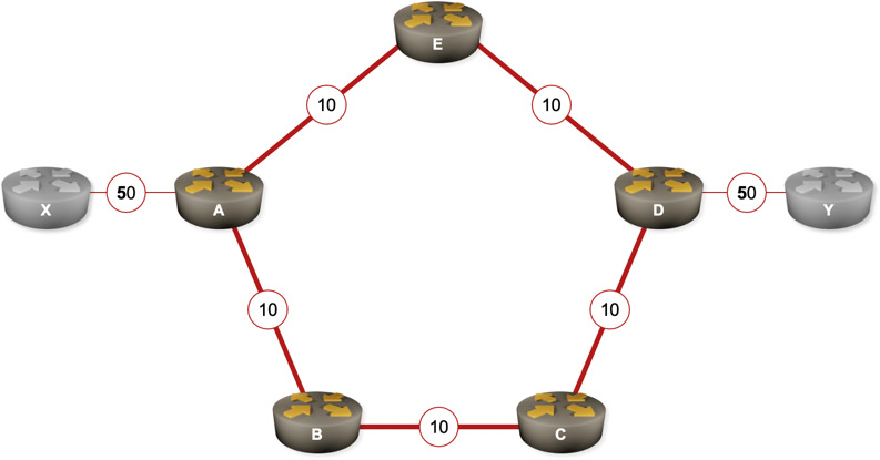
Sample MPLS TE network
IS-IS is used as the routing protocol in the network and the IS-IS circuit costs have been set to 10 on the core links and to 50 on the access links.
Link state database
Once the IS-IS adjacencies have been established and the link state information distributed between the routers, the information stored in the IS-IS topology database of router A represents the following graph:
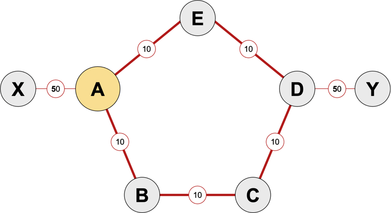
Link state topology graph
SPF tree built on router A
When the router A runs the SPF algorithm, the link between nodes C and D is not used in the shortest-path tree; all the traffic from router A to router Y flows through routers E and D.
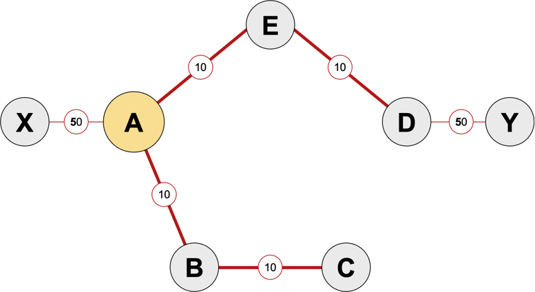
SPF tree created in router A
The traffic from router X to router Y also flows through routers E and D. A is the downstream router of router X; whatever routing decisions router X makes, once the packet arrives at router A, it’s forwarded using the CEF tables in router A.
Creation of an MPLS TE tunnel
The network operator might decide to create an MPLS TE tunnel between routers A and D to utilize the alternate path A-B-C-D.
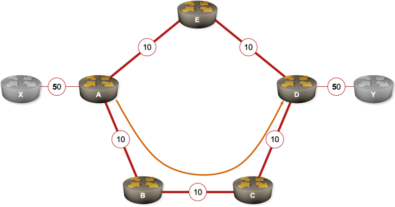
MPLS TE tunnel is created on router A
After the tunnel is created and the LSP from A to D is established, the tunnel interface state changes to up/up, but the tunnel is not yet used to forward the data traffic. The SPF tree in router A is not modified and although the tunnel is operational, it’s not used by the routing algorithm (IS-IS or OSPF) as there’s no router-to-router adjacency established over it.
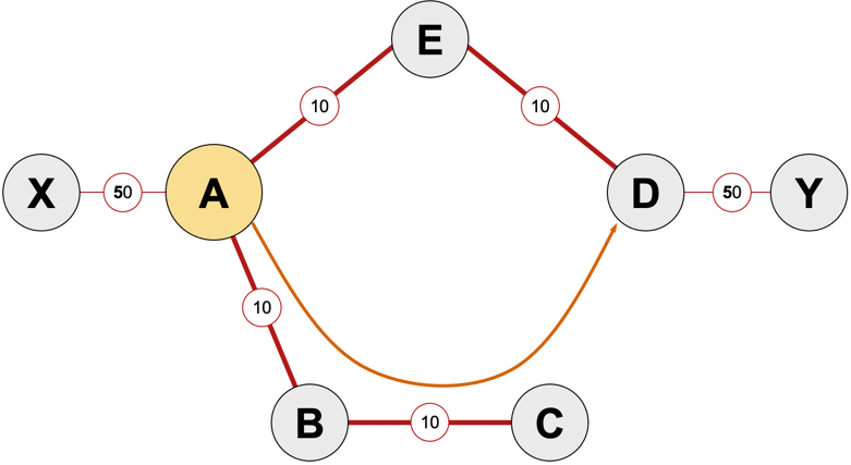
MPLS TE tunnel is ignored by the SPF algorithm
MPLS TE tunnel with autoroute
However, once the network operator enables autoroute functionality on the newly-created MPLS TE tunnel, the SPF algorithm uses the MPLS TE tunnel in its path calculation. After the SPF tree is built on router A, the path A-E-D is replaced by a direct link (MPLS TE tunnel) from A to D. From the perspective of router A, router D and all destinations beyond it reachable solely through the MPLS TE tunnel.
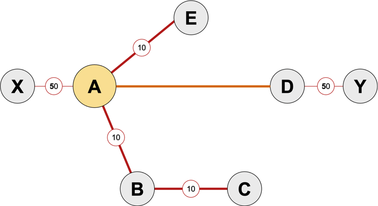
Autoroute MPLS TE tunnel is inserted in the SPF tree
The MPLS TE tunnel replaces the original path computed by the SPF algorithm; after the autoroute is enabled, all the traffic from A to D flows through the MPLS TE tunnel established on the path A-B-C-D.