Creating MPLS/VPN Labs With netlab
Two week ago I described how to create a simple VRF Lite lab with netlab VRF configuration module. Adding MPLS/VPN to the mix and creating a full-blown MPLS/VPN lab is a piece of cake. In this blog post we’ll build a simple topology with two VRFs (red and blue) and two PE-routers:
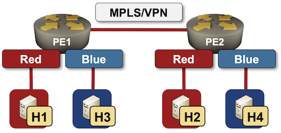
Lab topology
Nodes
We’ll need six nodes in the lab. Four of them will be Linux hosts, the two PE-routers will be Arista EOS devices. We’ll have to enable these configuration modules on the PE-routers:
vrffor obvious reasonsbgpbecause it’s needed to transport VPNv4 address family updates between PE-routersmplsto get LDP and BGP VPNv4 address familyospfbecause we’re building an IBGP design and need something to propagate loopback interface addresses.
defaults.device: eos

nodes:
  pe1:
    module: [ vrf,ospf,bgp,mpls ]
  pe2:
    module: [ vrf,ospf,bgp,mpls ]
  h1:
    device: linux
  h2:
    device: linux
  h3:
    device: linux
  h4:
    device: linux
We’ll use two VRFs, and let the tool automatically assign route distinguishers and route targets.
vrfs:
  red:
  blue:
Links
There are five links in our lab, four of them belong to VRFs, the fifth one connects PE1 and PE2:
links:
- pe1: { vrf: red }
  h1:
- pe2: { vrf: red }
  h2:
- pe1: { vrf: blue }
  h3:
- pe2: { vrf: blue }
  h4:
- pe1-pe2
Module Parameters
All we need now is a sprinkle of unicorn dust module parameters:
- BGP AS number is set to 65000
- LDP and VPNv4 are enabled within the MPLS module
bgp.as: 65000
mpls.ldp: True
mpls.vpn: True
And that’s it. Save the topology file into an empty directory, execute netlab up and you’ll have a full-blown MPLS/VPN lab.
Sample Configuration
Don’t trust me? Here are a few printouts:
pe1#show ip bgp vrf red
BGP routing table information for VRF red
Router identifier 10.0.0.1, local AS number 65000
Route status codes: s - suppressed, * - valid, > - active, E - ECMP head, e - ECMP
                    S - Stale, c - Contributing to ECMP, b - backup, L - labeled-unicast
                    % - Pending BGP convergence
Origin codes: i - IGP, e - EGP, ? - incomplete
RPKI Origin Validation codes: V - valid, I - invalid, U - unknown
AS Path Attributes: Or-ID - Originator ID, C-LST - Cluster List, LL Nexthop - Link Local Nexthop

          Network                Next Hop              Metric  AIGP       LocPref Weight  Path
 * >      172.16.0.0/24          -                     -       -          -       0       i
 * >      172.16.1.0/24          10.0.0.2              0       -          100     0       i
pe1#show ip route vrf red | begin Gateway
Gateway of last resort is not set

 C        172.16.0.0/24 is directly connected, Ethernet1
 B I      172.16.1.0/24 [200/0] via 10.0.0.2/32, LDP tunnel index 1, label 100000
                                   via 10.1.0.2, Ethernet3, label imp-null(3)
pe1#show mpls lfib route
MPLS forwarding table (Label [metric] Vias) - 3 routes
MPLS next-hop resolution allow default route: False
...
 B3    100000   [0]
                via I, ipv4, vrf blue
 B3    100001   [0]
                via I, ipv4, vrf red
 L     116384   [1], 10.0.0.2/32
                via M, 10.1.0.2, pop
                 payload autoDecide, ttlMode uniform, apply egress-acl
                 interface Ethernet3
Finally, here are the relevant parts of PE1 configuration as generated by netlab release 1.2.1:
vrf instance blue
   rd 65000:2
!
vrf instance red
   rd 65000:1
!
!
interface Ethernet1
   description pe1 -> [h1] [stub]
   vrf red
   ip address 172.16.0.1/24
   ip ospf network point-to-point
   ip ospf area 0.0.0.0
!
interface Ethernet2
   description pe1 -> [h3] [stub]
   vrf blue
   ip address 172.16.2.1/24
   ip ospf network point-to-point
   ip ospf area 0.0.0.0
!
interface Ethernet3
   description pe1 -> pe2
   ip address 10.1.0.1/30
   mpls ldp interface
   ip ospf network point-to-point
   ip ospf area 0.0.0.0
!
interface Loopback0
   ip address 10.0.0.1/32
   mpls ldp interface
   ip ospf area 0.0.0.0
!
ip routing
ip routing vrf blue
ip routing vrf red
!
mpls ip
!
mpls ldp
   router-id 10.0.0.1
   transport-address interface Loopback0
   interface disabled default
   no shutdown
!
router bgp 65000
   router-id 10.0.0.1
   bgp advertise-inactive
   neighbor 10.0.0.2 remote-as 65000
   neighbor 10.0.0.2 next-hop-self
   neighbor 10.0.0.2 update-source Loopback0
   neighbor 10.0.0.2 description pe2
   neighbor 10.0.0.2 send-community standard extended
   !
   address-family ipv4
      neighbor 10.0.0.2 activate
      network 10.0.0.1/32
   !
   address-family vpn-ipv4
      neighbor 10.0.0.2 activate
   !
   vrf blue
      rd 65000:2
      route-target import vpn-ipv4 65000:2
      route-target export vpn-ipv4 65000:2
      router-id 10.0.0.1
      redistribute connected
      redistribute ospf
   !
   vrf red
      rd 65000:1
      route-target import vpn-ipv4 65000:1
      route-target export vpn-ipv4 65000:1
      router-id 10.0.0.1
      redistribute connected
      redistribute ospf
!
router ospf 1
   router-id 10.0.0.1
   max-lsa 12000
!
router ospf 100 vrf red
   router-id 10.0.0.1
   interface unnumbered hello mask tx 0.0.0.0
   passive-interface Ethernet1
   redistribute bgp
   max-lsa 12000
!
router ospf 101 vrf blue
   router-id 10.0.0.1
   interface unnumbered hello mask tx 0.0.0.0
   passive-interface Ethernet2
   redistribute bgp
   max-lsa 12000
Build Your Own
You’ll find the lab topology file on GitHub. To use it:
- Install netlab and your preferred lab environment. These days I find it easiest to use Arista cEOS with containerlab, but the data plane (pings) probably won’t work.
- Copy topology files into an empty directory
- Execute netlab up with the parameters described above.
Thank you for your work on this project!
Hope you'll find it useful... and if there's some functionality you'd love to see implemented just open a GitHub issue.